Illuminating device and liquid crystal display

A technology for liquid crystal displays and lighting devices, applied in lighting devices, lighting device parts, lighting and heating equipment, etc., can solve the problems of low light utilization efficiency and increased cost, and achieve the effect of high utilization efficiency and low cost

Inactive Publication Date: 2008-01-02
KK TOSHIBA
View PDF1 Cites 65 Cited by
  • Summary
  • Abstract
  • Description
  • Claims
  • Application Information

AI Technical Summary

Problems solved by technology

[0006] However, the technology described in Patent Document 1 has the following problems: because the processing for providing the reflection sheet on the light guide plate is necessary, the cost increases, and at the same time, the light utilization efficiency is reduced due to the absorption of light by the reflection sheet. Low

Method used


Image

  • Illuminating device and liquid crystal display
  • Illuminating device and liquid crystal display
  • Illuminating device and liquid crystal display

Examples


Embodiment Construction

[0033] Embodiments of the present invention will be described below with reference to the accompanying drawings.

[0034] First, a first embodiment of the present invention will be described.

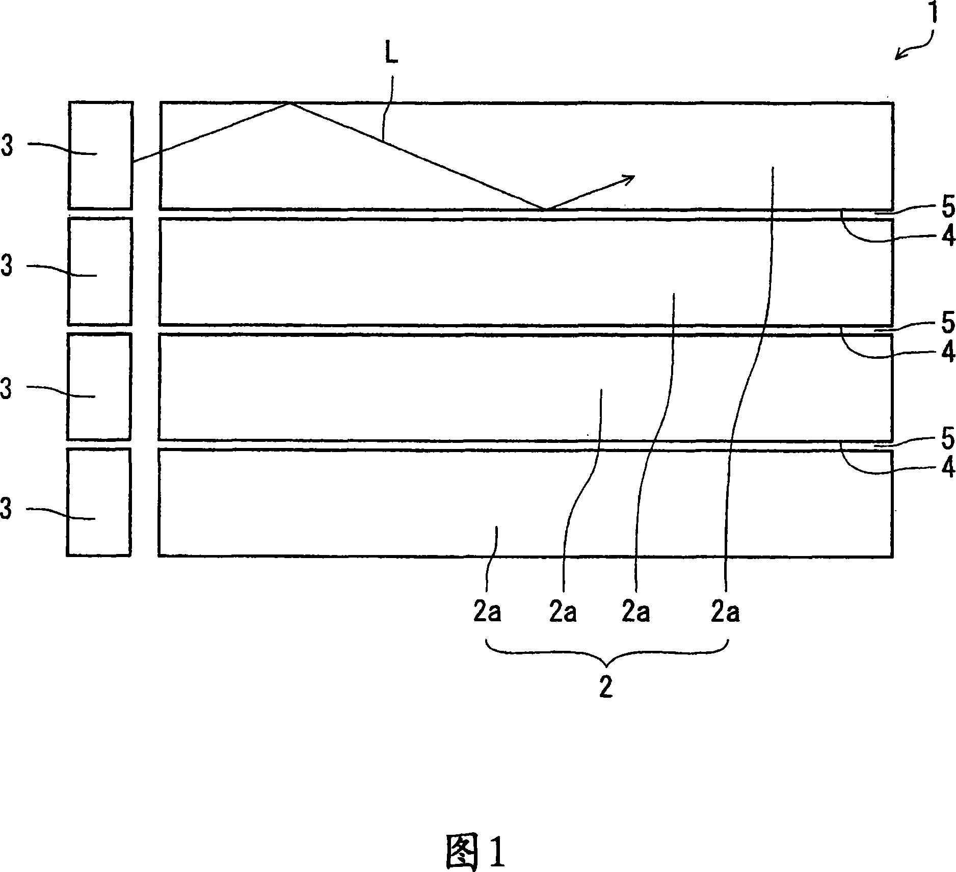
[0035] FIG. 1 is an optical model diagram illustrating an illumination device according to this embodiment.

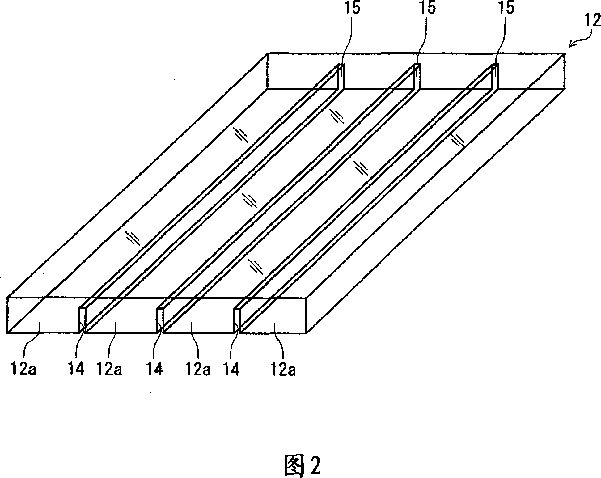
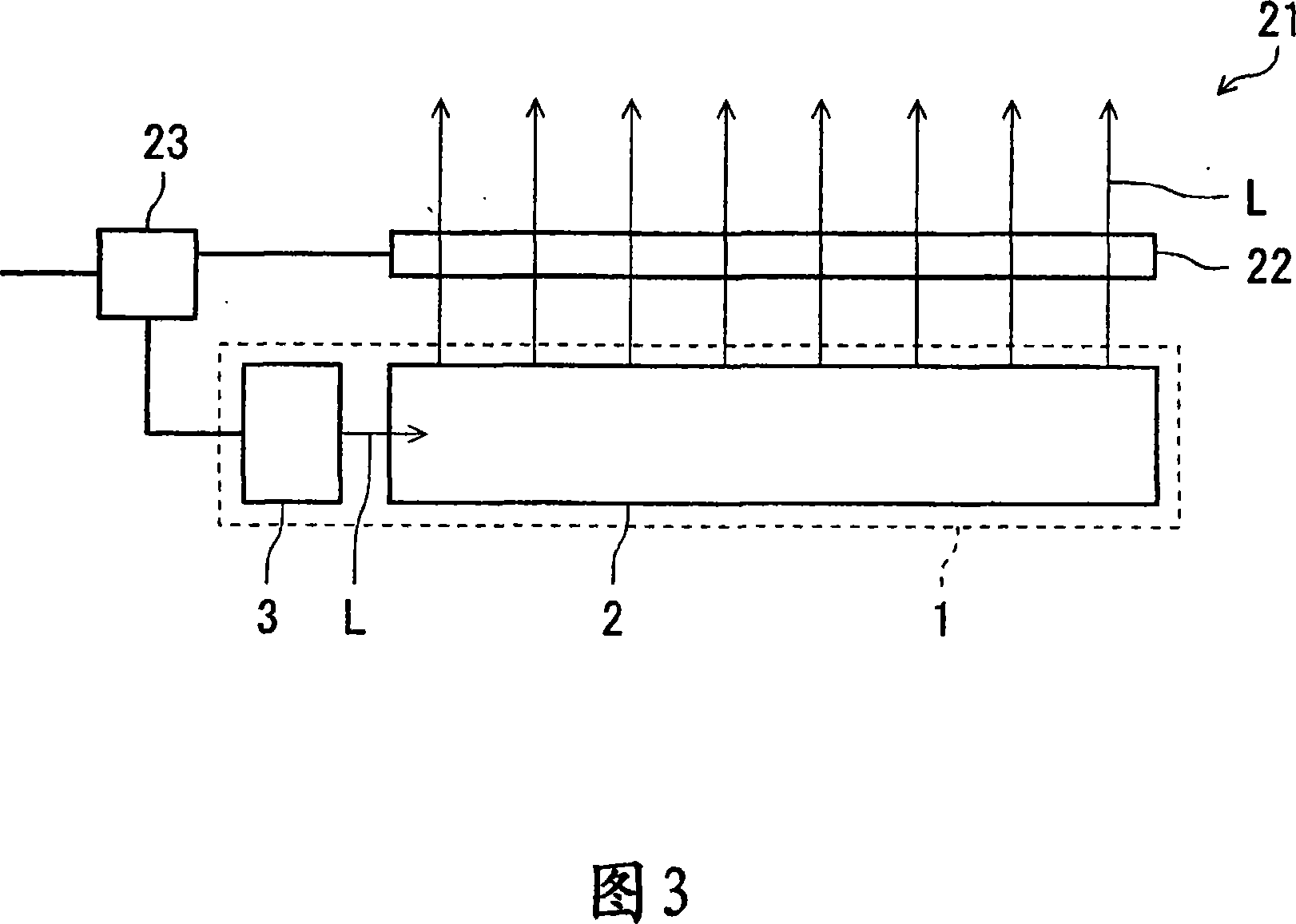
[0036] As shown in Figure 1, in the lighting device 1 of the present embodiment, a light guide plate 2 formed by a plurality of parts 2a arranged in a row is provided; a plurality of light sources 3, the plurality of light sources 3 for each part 2a And it is provided that the member 2a is irradiated with light. In addition, a gap 4 of 0.1 μm or more is formed in at least a part of the region between the adjacent members 2 a, and the inside of the gap 4 is an air layer 5 . In addition, a prism or a pattern (not shown) for diffusing light is formed on at least one of the top surface and the bottom surface of the light guide plate 2 .

[0037] In the present embodiment, if one ...


PUM


Abstract

An illumination apparatus includes: a light guide plate composed of a plurality of aligned blocks; and a plurality of light sources, each being provided for one of the blocks and emitting light to the one block. A gap of 0.1 microns or more is formed in at least part of a region between the adjacent blocks. An inside of the gap serves as an air layer.

Description

technical field [0001] The present invention relates to an illuminating device and a liquid crystal display, and particularly to an illuminating device that emits light from a light source in planar form through a light guide plate, and a quasi-pulse liquid crystal display equipped with the illuminating device. Background technique [0002] In recent years, a liquid crystal display (hereinafter referred to as "LCD" (Liquid Crystal Display)) has rapidly spread as a thin display. However, compared with CRT (Cathode-Ray Tube: cathode ray tube) displays (hereinafter referred to simply as "CRT"), LCDs have problems of blurred motion pictures and low contrast. That is, in the CRT, there is a non-light-emitting period in which the pixel does not emit light between the light-emitting period of the pixel of a certain frame and the light-emitting period of the pixel of the next frame, so there is little residual image feeling. On the other hand, the LCD display method is a "hold type...

Claims


Application Information

Patent Timeline
Patent Type & Authority Applications(China)
IPC IPC(8): F21V8/00F21V19/00G02F1/13357G02F1/33G02F1/1335
Inventor 冈田直忠
Owner KK TOSHIBA
Why Eureka
Try Eureka