Test cabinet of double testing antenna

A technology for testing antennas and double testing, which is applied in the field of testing rooms, can solve problems such as questioning the accuracy of test results and differences in test results, and achieve the effects of reducing R&D and production costs and reducing test errors

Inactive Publication Date: 2008-01-02
MITAC COMP (SHUN DE) LTD +1
View PDF0 Cites 19 Cited by
  • Summary
  • Abstract
  • Description
  • Claims
  • Application Information

AI Technical Summary

Problems solved by technology

[0007] That is to say, in the existing test room, the tester will change the test antenna during the test to perform EMC test or RF test. However, the sensitivity of RF test is quite high, and even a little movement will have a considerable impact on the test results. discrepancy, so the test results obtained are easily questionable about their accuracy

Method used


Image

  • Test cabinet of double testing antenna
  • Test cabinet of double testing antenna
  • Test cabinet of double testing antenna

Examples


Embodiment Construction

[0025] Specific embodiments are listed below to describe the content of the present invention in detail, and illustrations are used as auxiliary descriptions. The symbols mentioned in the description refer to the symbols of the drawings.

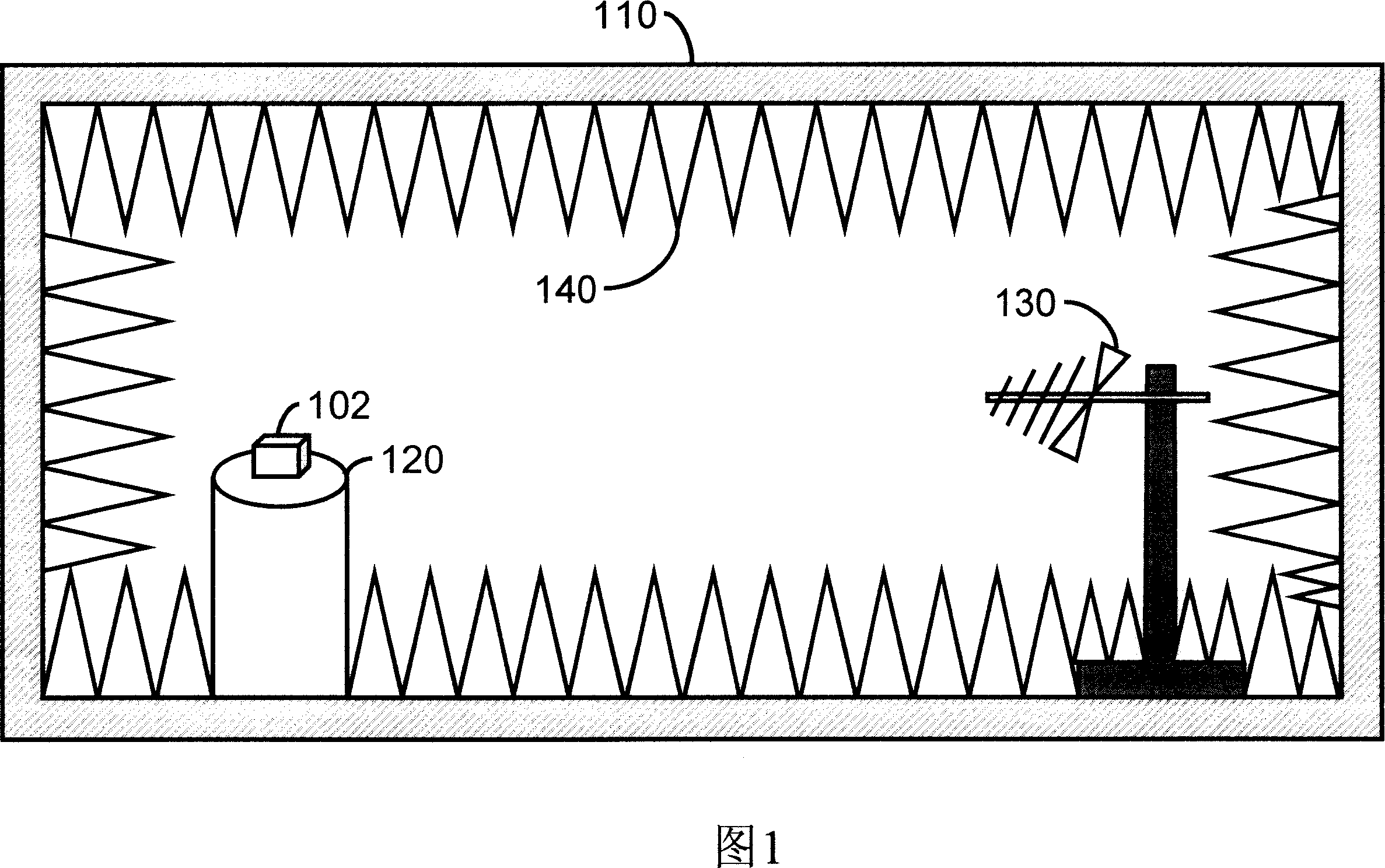
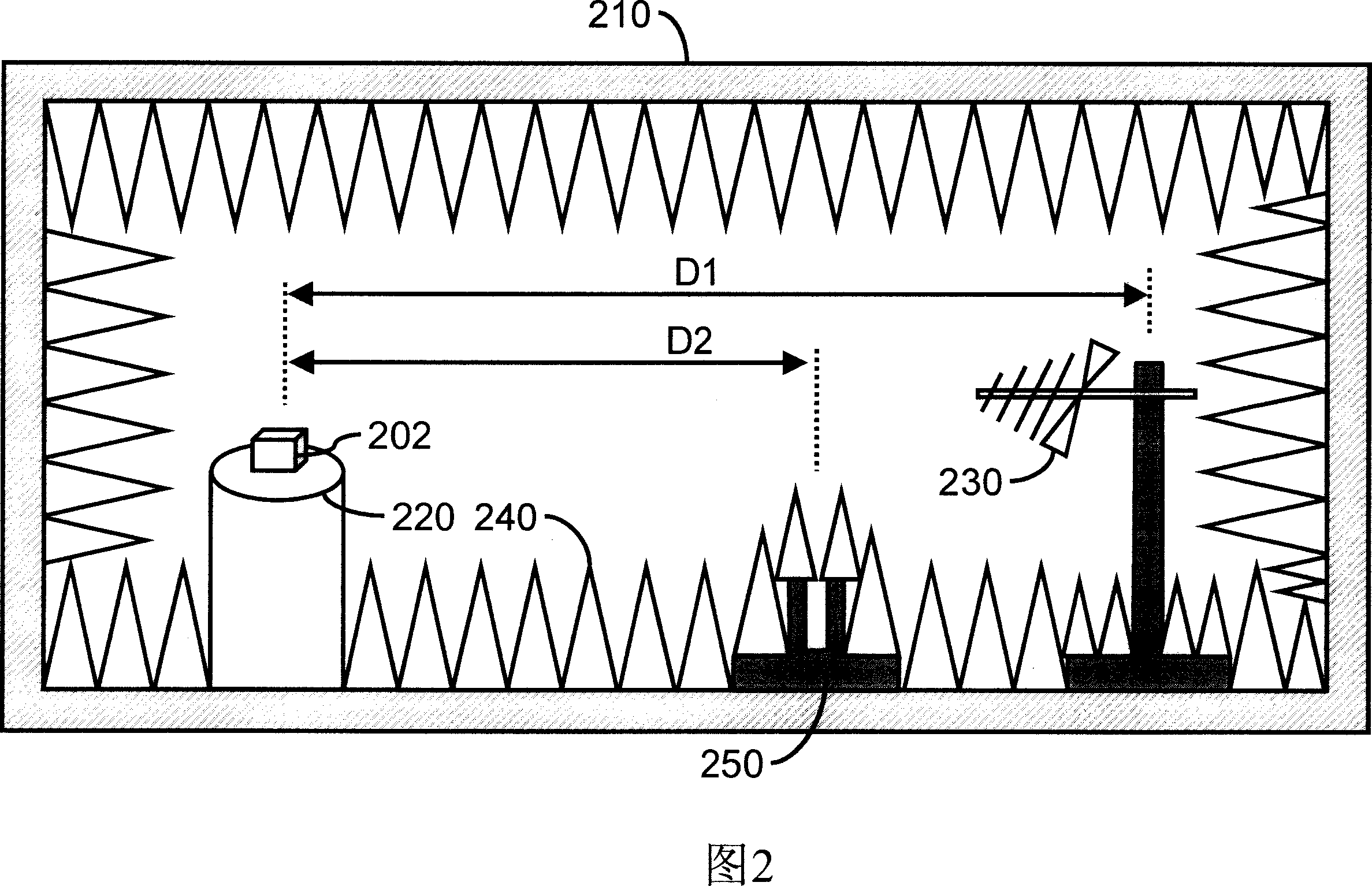
[0026] Please refer to FIG. 2 , which is a test room with double test antennas according to an embodiment of the present invention, which is used to carry out an electromagnetic wave-related test of an electronic device, and mainly includes an isolation room 210, a test table 220, a first test antenna 230, Several absorbing materials (Absorber) 240 and an antenna frame 250 . The test table 120 , the antenna rack 250 and the first test antenna 230 are sequentially arranged in the isolation room 210 . Wherein, the first test antenna 230 is apart from the test table 120 by a first predetermined distance D1, and the antenna stand 250 is also apart from the test table 120 by a second predetermined distance D2, wherein the first and second predet...


PUM


Abstract

A kind of testing room of double testing antenna is used to test electromagnetic wave of electronic device; it mainly possesses an antenna rack which a testing antenna can be mounted selectively, so the two relative tests of electromagnetic wave can share a testing room, and test error induced by moving testing antenna can be decreased.

Description

【Technical field】 [0001] The invention relates to a testing room for electromagnetic wave related testing, especially a testing room with double testing antennas. 【Background technique】 [0002] With the advancement of technology, all kinds of computer (Computer), communication (Communication) and consumer electronics (Customer Electronic) integrated system equipment are developing rapidly to bring people more convenient life. However, with the widespread use of related products of electronic and electrical equipment, a relatively complex electromagnetic noise environment is created. [0003] Therefore, all related products of electronic and electrical equipment must comply with relevant electromagnetic compatibility (Electromagnetic Compatibility; EMC) standards and specifications before they can be sold. Electromagnetic compatibility testing is divided into electromagnetic interference and electromagnetic tolerance testing. Therefore, during the entire product development...

Claims


Application Information

Patent Timeline
Patent Type & Authority Applications(China)
IPC IPC(8): G01R29/08G01R31/00
Inventor 杨华青
Owner MITAC COMP (SHUN DE) LTD
Why Eureka
Try Eureka