
Image forming apparatus

A technology of image and usage, applied in corona discharge device, electric recording process applying charge pattern, equipment applying electric recording process of charge pattern, etc. Achieve the effect of efficient second bias correction operation

Inactive Publication Date: 2008-01-02
KYOCERA DOCUMENT SOLUTIONS INC
View PDF1 Cites 1 Cited by
  • Summary
  • Abstract
  • Description
  • Claims
  • Application Information

AI Technical Summary

Problems solved by technology

But there is a problem in this method: when the resistance value of the charging roller is greatly increased, it takes a long time until the amount of change is less than the threshold value, that is, the resistance value stabilizes, and it takes a long time until the image forming action starts (so-called mature time). time) can become very long
Therefore, the desired surface potential cannot be obtained even if the charging current is detected and bias correction is performed.

Method used


Image

  • Image forming apparatus
  • Image forming apparatus
  • Image forming apparatus

Examples


Embodiment Construction

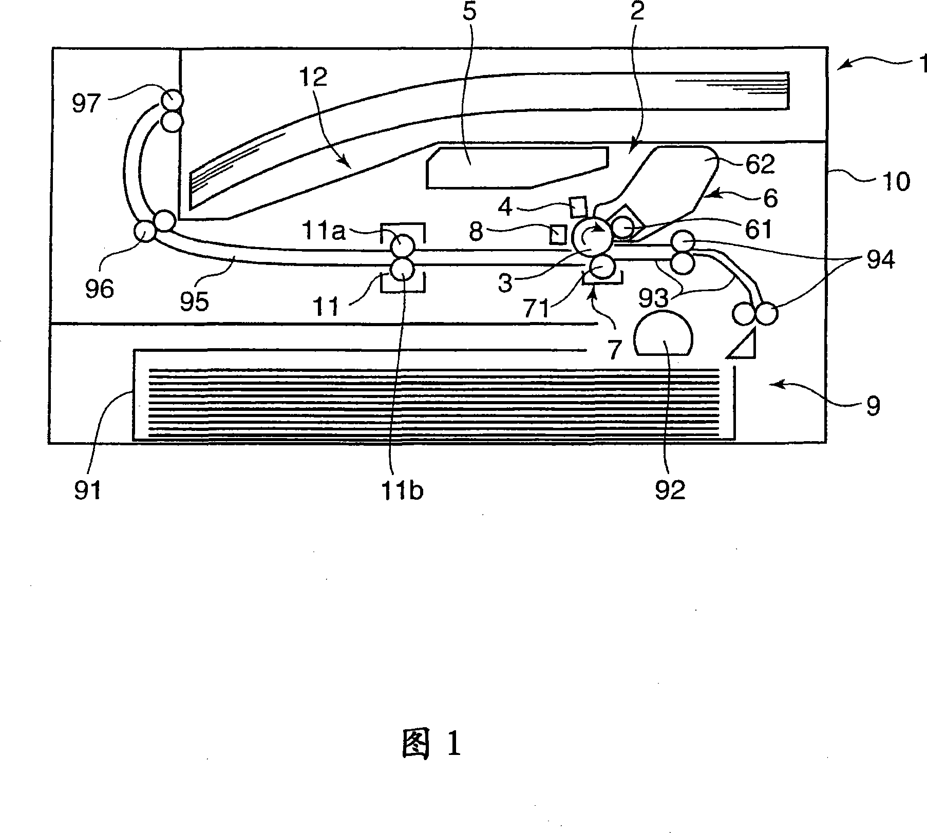
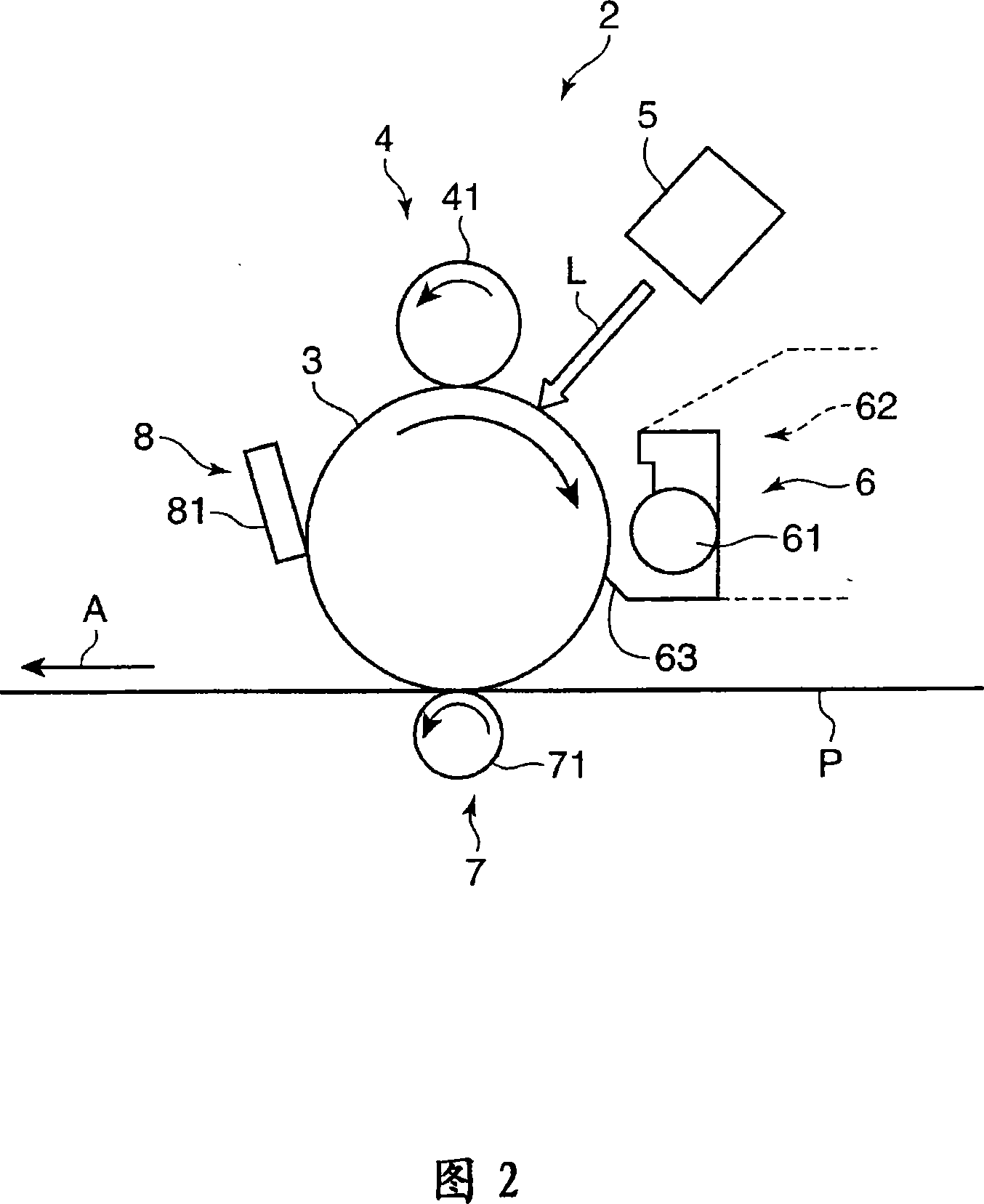
[0020] 1 is a cross-sectional view schematically showing the internal structure of an image forming apparatus (printer) according to an embodiment of the present invention. The image forming apparatus of the present invention is aimed at a multifunctional machine, a printer, a facsimile, etc., which develop an electrostatic latent image using toner by electrophotography. In this embodiment, a printer 1 will be described as the image forming apparatus. The printer 1 is provided with an image forming unit 2 inside a printer main body 10 . As shown in the figure, the image forming section 2 forms an image on paper, and includes: a photosensitive drum 3, a charging section 4 arranged around the photosensitive drum 3, an exposure section 5, a developing section 6, a transfer section 7, and a cleaning section. Part 8.

[0021] FIG. 2 is a partial enlarged view schematically showing the image forming unit 2 . The photosensitive drum 3 is an image carrier rotatably supported in the...


PUM


Abstract

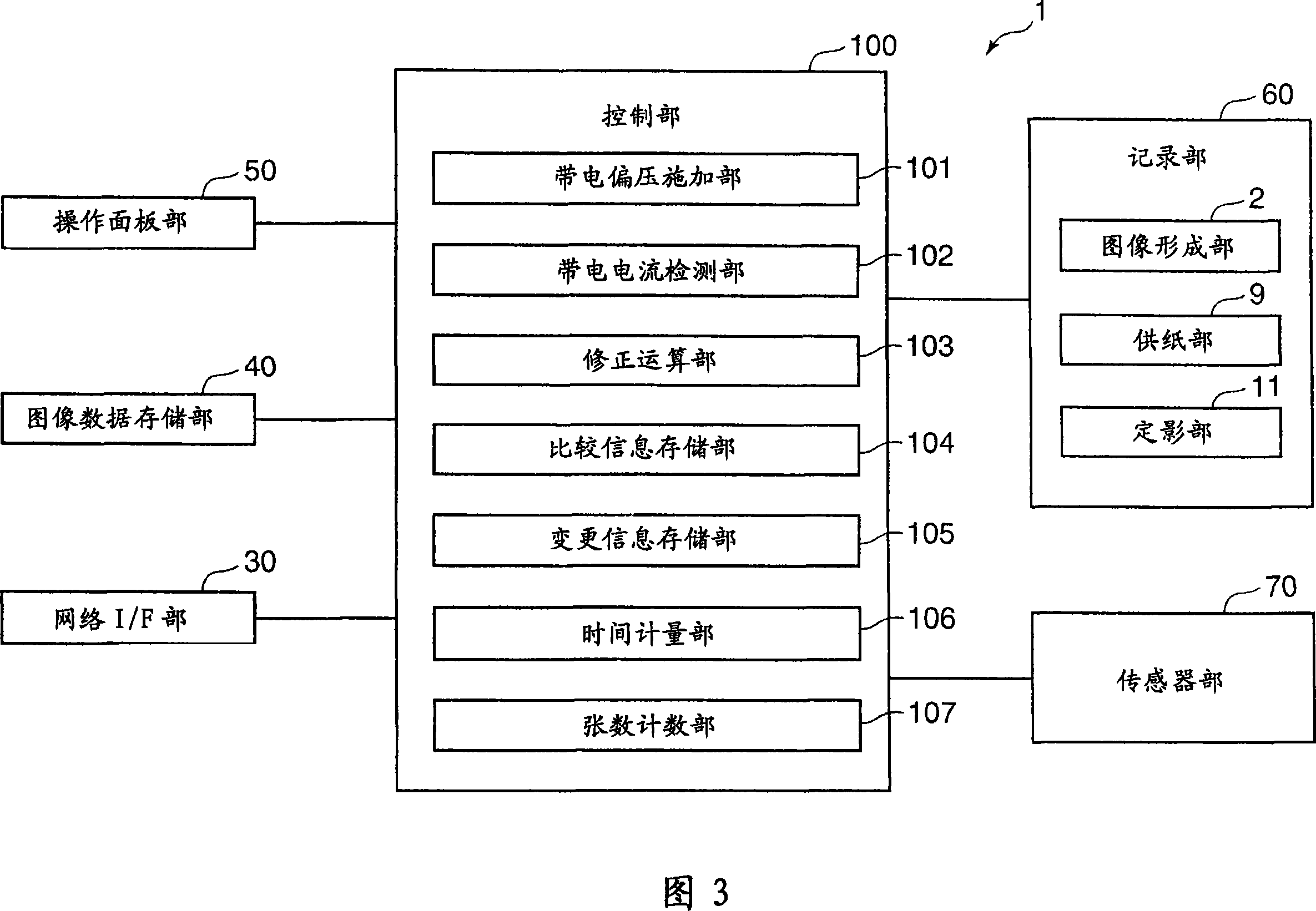
An image forming apparatus charges the surface of a photosensitive member to a predetermined potential. A current detector detects a charging current when the charging bias is applied. A storage stores a target charging current value when the photosensitive member is charged to a required potential. A usage acquiring portion acquires information relating to usage of the charging roller. A bias corrector performs first and second corrections. The first correction compares a charging current value with a stored target charging current value and determines a new charging bias based on the comparison. The second correction determines whether usage of the charging roller is a predetermined first amount or a greater amount based on acquired usage information, and when the usage is the greater amount, changes the target charging current value in accordance with the usage amount and obtains a new charging bias based on the changed target charging current value.

Description

technical field [0001] The present invention relates to an image forming apparatus having a function of charging the surface of a photoreceptor with a charging roller, and more particularly to an image forming apparatus capable of correcting a charging bias. Background technique [0002] In recent years, as a charging mechanism of an image forming apparatus using an electrophotography system, a charging roller system having a feature of suppressing ozone generation has been widely used. The electrical resistance of the charging roller changes depending on the environment or the lifespan. Therefore, in order to apply an optimum bias voltage to the charging roller according to the change in resistance, a method of determining the output bias voltage based on the detection result of the charging current has been proposed. [0003] However, it is very difficult to accurately detect the charging current. The reason for saying this is because the current (charging current) in the...

Claims


Application Information

Patent Timeline
Patent Type & Authority Applications(China)
IPC IPC(8): G03G15/02G03G15/00
CPCG03G15/0266G03G2215/021
Inventor 宫地信希丸山佳彦
Owner KYOCERA DOCUMENT SOLUTIONS INC
Learn More