
Display device driving apparatus and display device using the same

一种驱动装置、显示装置的技术,应用在静态指示器、非线性光学、光学等方向,能够解决不能切换控制等问题,达到降低串扰、提高显示品质的效果

Inactive Publication Date: 2006-05-24
ROHM CO LTD
View PDF3 Cites 0 Cited by
  • Summary
  • Abstract
  • Description
  • Claims
  • Application Information

AI Technical Summary

Problems solved by technology

Therefore, there is a problem that a circuit mechanism for generating the timing signal is required, and there is also the problem that corresponding switching control cannot be performed according to voltage fluctuations.

Method used


Image

  • Display device driving apparatus and display device using the same
  • Display device driving apparatus and display device using the same
  • Display device driving apparatus and display device using the same

Examples


Embodiment Construction

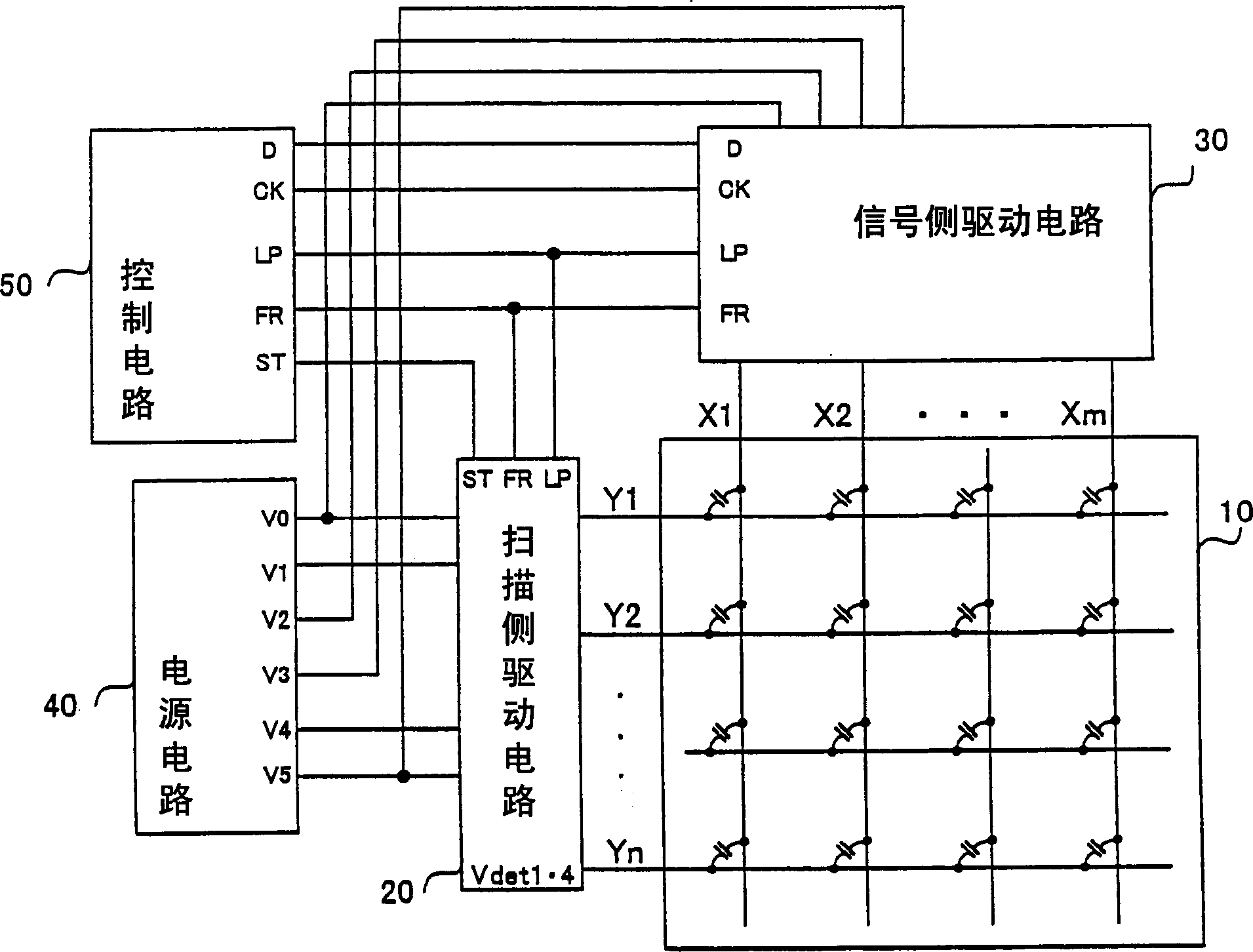
[0049] Hereinafter, embodiments of the drive device for a display device and the display device using the drive device according to the present invention will be described with reference to the drawings by taking a liquid crystal display device as an example. figure 1 It is a diagram showing a schematic configuration of a liquid crystal display device according to an embodiment of the present invention, and includes a matrix display 10 , a scanning-side driving circuit 20 , a signal-side driving circuit 30 , a power supply circuit 40 , and a control circuit 50 . In addition, as a display device, an organic EL display device using an organic EL display element can be used.

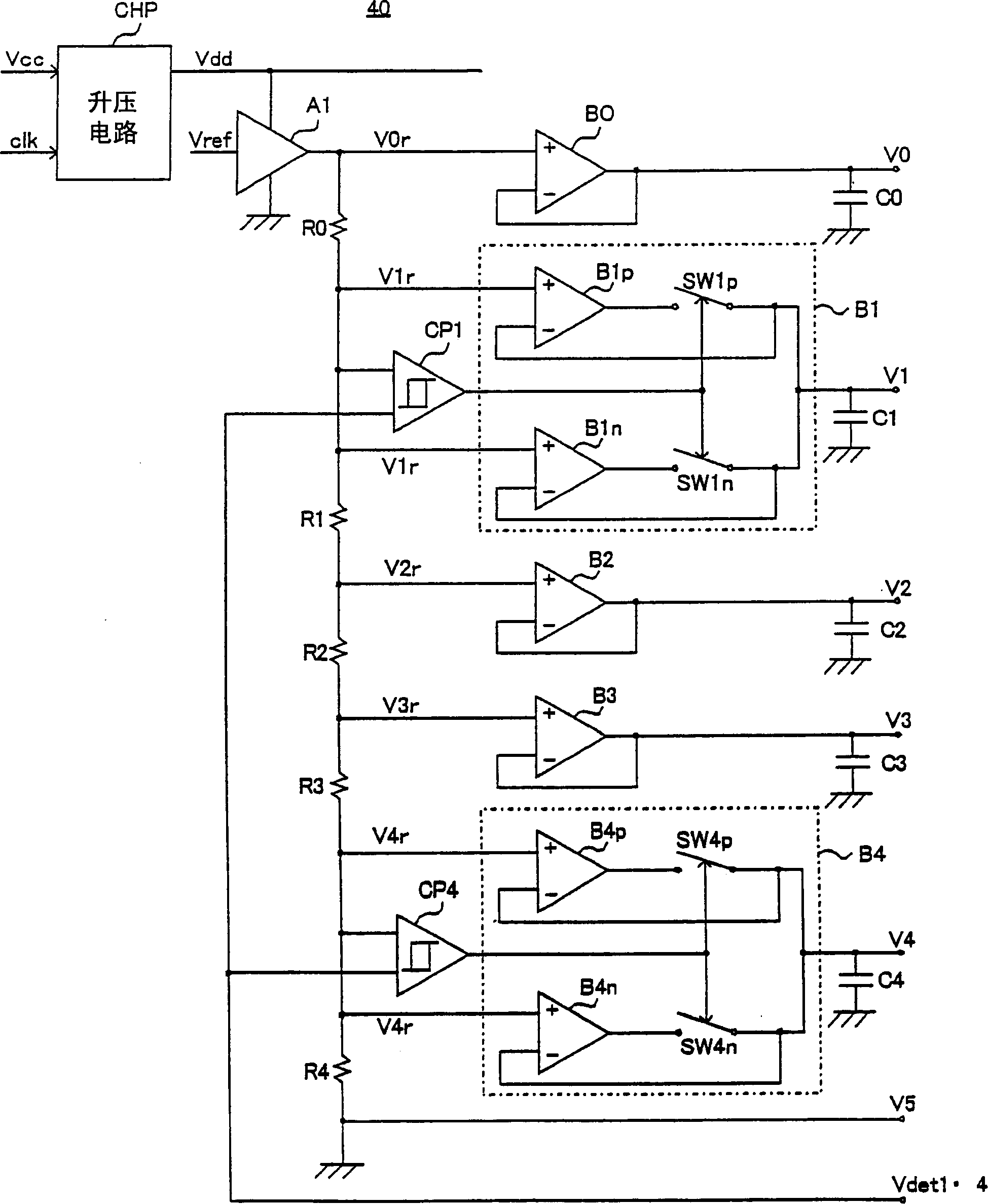
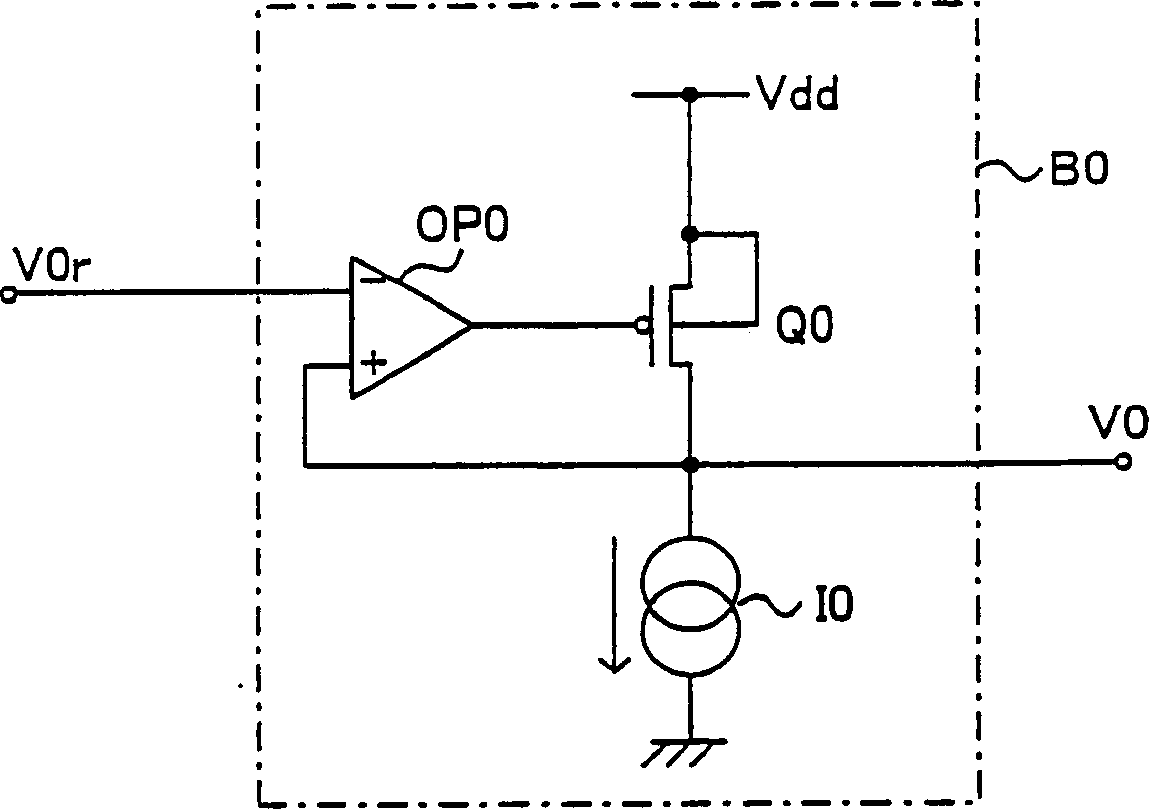
[0050] figure 2 It is a configuration diagram of the power supply circuit 40 . Figure 3A ~ Figure 3E It is a diagram showing the configuration of each snubber circuit in the power supply circuit. Figure 4A , Figure 4B , is a graph showing the operating characteristics of each voltage comparator in t...


PUM


Abstract

Provided is a driving device for a matrix display device, wherein a predetermined buffer circuit (B1) in a power supply circuit has a second function of increasing the driving capability of an output current to a high-level side so as to always generate the same output voltage (V1). 1 output circuit (B1p) and a 2nd output circuit (B1n) which improves the drive capability of the output current to the low level side. And, after comparing the detection voltage (Vdet1·4) of the detection position connected to the output terminal of the buffer circuit (B1) and the bias voltage (V1r), switch between the first and second output circuits (B1p, B1n). output and provided to the display. In this way, crosstalk is reduced and display quality is improved.

Description

technical field [0001] The present invention relates to a display device driving device for driving a display device such as a matrix type liquid crystal display device, and a display device using the same. Background technique [0002] As a liquid crystal display device for realizing dot representation, a matrix type liquid crystal display device in which a large number of strip-shaped row electrodes (scanning electrodes: common electrodes) and column electrodes (signal electrodes: segment electrodes) are arranged orthogonally to each other is often used. [0003] This liquid crystal display device displays an image by sequentially applying a scanning voltage to each scanning electrode and simultaneously applying a signal voltage to a plurality of signal electrodes while applying a voltage to the scanning electrode. Each liquid crystal element is formed at the intersection of each scanning electrode and each signal electrode. [0004] Each liquid crystal element is control...

Claims


Application Information

Patent Timeline
Patent Type & Authority Applications(China)
IPC IPC(8): G02F1/133G09G3/36G09G3/20
CPCG09G3/3696G09G2320/0209G09G3/36G09G3/20G02F1/133
Inventor 故岛秀数
Owner ROHM CO LTD
Learn More