
Method for regulating the maximum speed of a working machine and associated hydrodynamic coupling

A technology of hydraulic coupling and working machinery, applied in the direction of clutches, clutches, mechanical equipment, etc., can solve the problem of reducing the maximum speed of air compressors, the structure of hydraulic shift couplers is complex, and it is not suitable for monitoring the speed of working machinery, etc. question

Inactive Publication Date: 2008-01-02
VOITH TURBO GMBH & CO KG
View PDF1 Cites 3 Cited by
  • Summary
  • Abstract
  • Description
  • Claims
  • Application Information

AI Technical Summary

Problems solved by technology

[0003] The known fill level adjustment devices are complex in terms of device construction and require different adjustment components, such as pressure sensors, valves and / or scoop tubes
Especially when the fluid coupling is installed in a motor vehicle, advantageously in the drive train between the air compressor and the drive engine, in order to be able to turn the air compressor on or off while reducing vibrations and avoid torque from The air compressor is transmitted to the driving engine or the transmission of the driving engine. The structure of the known filled and adjusted hydraulic shift coupling is too complicated, and it is not very suitable for monitoring the rotational speed of the working machine, especially the air compressor. speed of
[0004] Another possible solution for limiting the maximum speed of the motor vehicle air compressor may be to intervene in the engine speed by controlling the engine, thereby limiting or reducing the maximum speed of the motor vehicle air compressor
However, since the motor vehicle engine is primarily used to drive the motor vehicle, and the engine is to be operated as energy-efficient as possible, such preemptive interventions in the engine speed due to the boundary conditions of the motor vehicle's compressed air system are undesirable

Method used


Image

  • Method for regulating the maximum speed of a working machine and associated hydrodynamic coupling
  • Method for regulating the maximum speed of a working machine and associated hydrodynamic coupling

Examples


Embodiment Construction

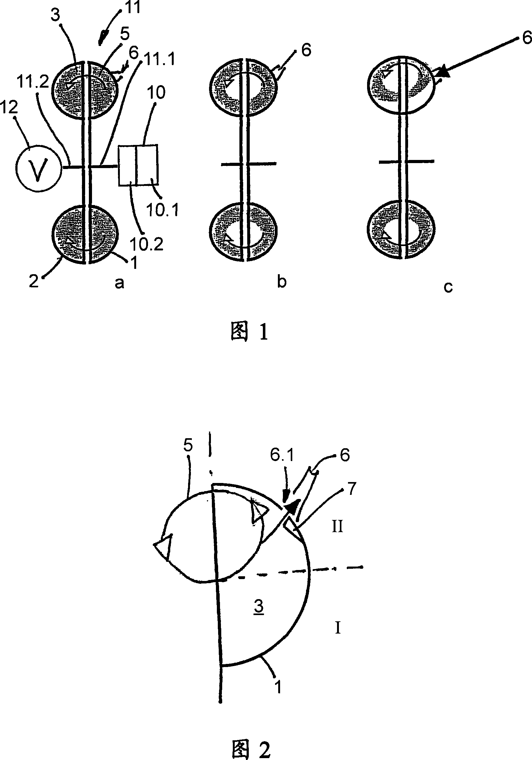
[0021] FIG. 1 schematically shows a fluid coupling 11 , which is inserted into a drive connection between an engine 10 and a working machine 12 . The engine 10 here comprises an internal combustion engine 10.1 having a transmission 10.2 connected thereto. The output shaft of the transmission 10.2 is connected to the input 11.1, which includes the pump wheel 1 of the fluid coupling 11. The output 11.2 of the hydrodynamic coupling including the turbine 2 is connected to a working machine 12, which is an air compressor. Of course, other transmissions or transmissions can be provided in the connection between the engine 10 or the transmission 10.2 and the pump wheel 1, respectively, and in the connection between the turbine 2 and the working machine 12, in order to set the desired rotational speed Compare. It is also possible to have an additional transmission or transmission only on one side of the coupling 11 .

[0022] FIG. 1 a schematically shows the state of the hydrodynam...


PUM


Abstract

The invention relates to a method for regulating the maximum speed of a working machine (12), in particular an air compressor in a vehicle. Said working machine is driven by means of a motor (10), using a hydrodynamic coupling (11), which comprises a working chamber (3) that is partially or fully filled with a working medium for transmitting a torque from a drive side (11.1) equipped with an impeller (1) to a driven side (11.2) equipped with a turbine wheel (2). The method comprises the following steps: the speed of the working machine, of the driven side of the hydrodynamic coupling, of the drive side of the hydrodynamic coupling and / or of the motor is detected; a maximum permissible value for the speed is defined and compared to the detected speed; if the detected speed exceeds the maximum permissible value, the quantity of working medium in the working chamber of the hydrodynamic coupling is automatically reduced by the opening or passage of medium through an outlet that is connected to the working chamber.

Description

technical field [0001] The invention relates to a method for adjusting the maximum rotational speed of a working machine driven by a motor via a fluid coupling. The invention relates in particular to a method for adjusting the rotational speed of an air compressor in a motor vehicle which is driven by a drive engine of the motor vehicle, in particular by an internal combustion engine, via a fluid coupling and which is designed, for example into a piston compressor for the compressed air system of a motor vehicle. Background technique [0002] It is known to regulate the rotational speed of a working machine by adjusting the fill level of a fluid coupling connected between the working machine and the engine driving the working machine, see for example publication WO 98 / 32987. In this case, the filling control is basically realized by interrupting the delivery of the working medium when the working chamber has reached the maximum filling degree. [0003] The known fill rate ...

Claims


Application Information

Patent Timeline
Patent Type & Authority Applications(China)
IPC IPC(8): F16D33/10
CPCF16D33/10F16D33/06F16D33/16
Inventor 马库斯·克莱库尔特·阿德勒夫赖因霍尔德·皮蒂乌斯
Owner VOITH TURBO GMBH & CO KG
Learn More