
Hydrodynamic clutch

A technology of hydraulic coupling and coupling, applied in the direction of clutch, clutch, fluid clutch, etc.

Active Publication Date: 2010-03-31
VOITH PATENT GMBH
View PDF0 Cites 13 Cited by
  • Summary
  • Abstract
  • Description
  • Claims
  • Application Information

AI Technical Summary

Problems solved by technology

This leads to structural problems on two fronts: Firstly, a storage chamber must be provided inside the coupler, which contains a working medium which should not remain in the working chamber due to the desired operating state
Conventional couplers are not yet adequate for these requirements

Method used


Image

  • Hydrodynamic clutch
  • Hydrodynamic clutch
  • Hydrodynamic clutch

Examples


Embodiment Construction

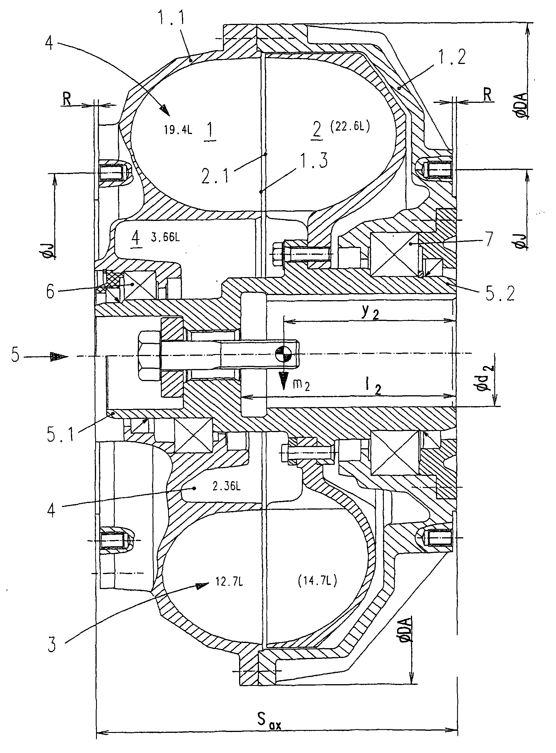
[0021] As is immediately apparent, the installation dimensions of the improved fluid coupling according to the invention correspond to those of conventional fluid couplings.

[0022] The pump impeller 1 and the turbine wheel 2 can be seen here, which together form the working chamber 3 . Furthermore, a storage chamber 4 can also be seen, which serves as a collection chamber for working medium that is not required in the working chamber. The storage chamber extends completely radially within the working chamber 3 in the axial direction of the hydrodynamic coupling. Specifically, seen in the axial direction, the storage chamber 4 extends from the middle of the turbine wheel 2 over the extent of the working chamber 3 arranged in the pump impeller 1 until there is a The defined distance, which is for example 10 mm, is generally between 5 and 20 mm, particularly advantageously between 8 and 12 mm.

[0023] The pump impeller 1 surrounds the turbine 2 together with the casing 1.2. ...


PUM


Abstract

The invention relates to a hydrodynamic clutch with a constant or variable filling of working medium, - having a pump wheel comprising a pump wheel blade arrangement, and - having a turbine wheel comprising a turbine wheel blade arrangement; - the pump wheel and turbine wheel together form a toroidal working chamber which, for torque transmission, can be filled with the working medium; - having anaccumulating chamber for receiving working medium from the working chamber, wherein the accumulating chamber is connected in a working-medium-conducting fashion to the working chamber; - the workingmedium can be conducted from the accumulating chamber into the working chamber in order to increase the transmissible torque, and from the working chamber into the accumulating chamber in order to reduce the transmissible torque. The hydrodynamic clutch is characterized in that the ratio of the volume of the working space to the installation volume of the hydrodynamic clutch is greater than 0.26,wherein the installation volume of the hydrodynamic clutch is defined by a cylinder volume which has a constant diameter and whose outer diameter corresponds to the maximum outer diameter of the hydrodynamic clutch and whose axial length corresponds to the maximum axial extent of the hydrodynamic clutch.

Description

technical field [0001] The invention relates to a hydrodynamic coupling with a constant or variable filling degree according to the preamble of claim 1 . Background technique [0002] The skilled person distinguishes between hydraulic couplings with a constant filling degree and couplings that can be filled and emptied. In the last-mentioned coupler, depending on the desired filling state, the working medium is fed from the outer circuit into the working chamber of the coupler or out of it, while in the first-mentioned coupler the working medium is always left in the coupling within the device. This leads to structural problems on two fronts: First, a storage chamber must be provided within the coupler, which contains a working medium which, due to the desired operating state, should not remain in the working chamber. Furthermore, the working medium heated by fluid friction cannot be cooled in the external heat exchanger, as is usually arranged in the external working medi...

Claims


Application Information

Patent Timeline
IPC IPC(8): F16D33/06
CPCF16D33/06
Inventor 哈拉尔德·霍费尔德
Owner VOITH PATENT GMBH
Learn More