Pruning machine

A technology of a pruning machine and a casing, applied in the field of pruning machines, can solve the problems of reduced friction between bushings and gears, weakened elastic effect of a disc spring, and users cannot make quick judgments, etc., and achieves strong elastic automatic compensation capability, The effect of reliable work

Active Publication Date: 2008-01-09
NINGBO ENERGY POWER TOOLS
View PDF0 Cites 11 Cited by
  • Summary
  • Abstract
  • Description
  • Claims
  • Application Information

AI Technical Summary

Problems solved by technology

Although the above-mentioned utility model has a certain unloading function, it still has the disadvantages: there must be a certain axial pressure between the friction plate, the gear and the disc spring to make the gear move through the action of the disc spring and the friction plate. Drive the bushing to rotate, after the friction plate slips and wears during the use of the pruning machine, the axial pressure between the friction plate, gear and disc spring will gradually decrease; moreover, due to the elasticity of the disc spring on the axial dimension The sensitivity is relatively large, so after the pruning machine slips and wears, the elastic effect of the disc spring will gradually weaken, so that the friction between the bushing and the gear decreases, and eventually the pruning machine has an unloading function. However, it can easily slip when subjected to a small external force, so that the pruning machine cannot work normally and reliably.
[0004] In addition, when using the pruning machine outdoors, users often encounter such a problem, that is, when the pruning machine is plugged into the socket and the switch is turned on, the pruning machine cannot operate normally, but the user cannot quickly judge that it is the pruning machine. The problem, or the problem of the power supply, which has brought some inconvenience to the user

Method used


Image

  • Pruning machine
  • Pruning machine

Examples


Embodiment Construction

[0016] The present invention will be further described below in conjunction with accompanying drawing and specific embodiment:

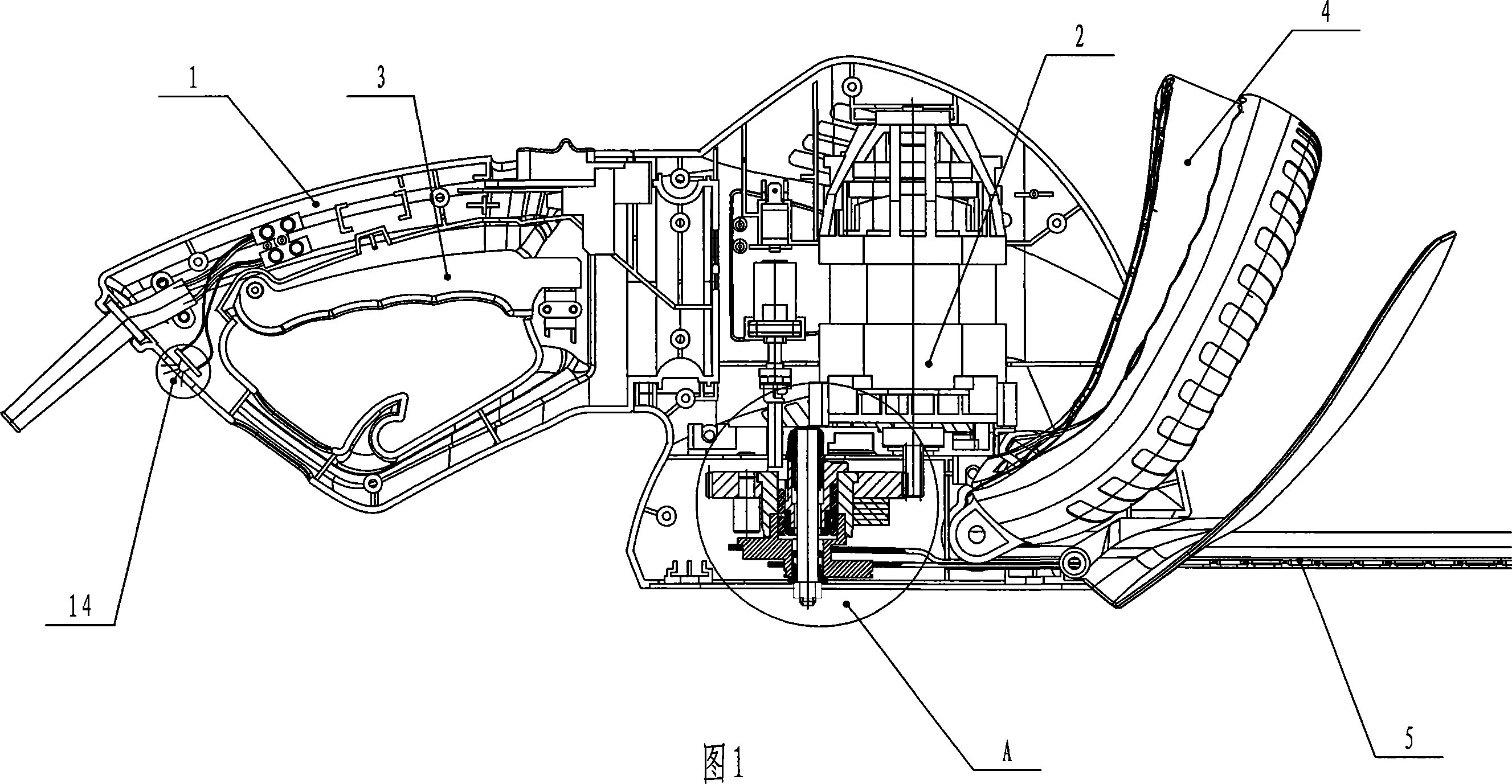
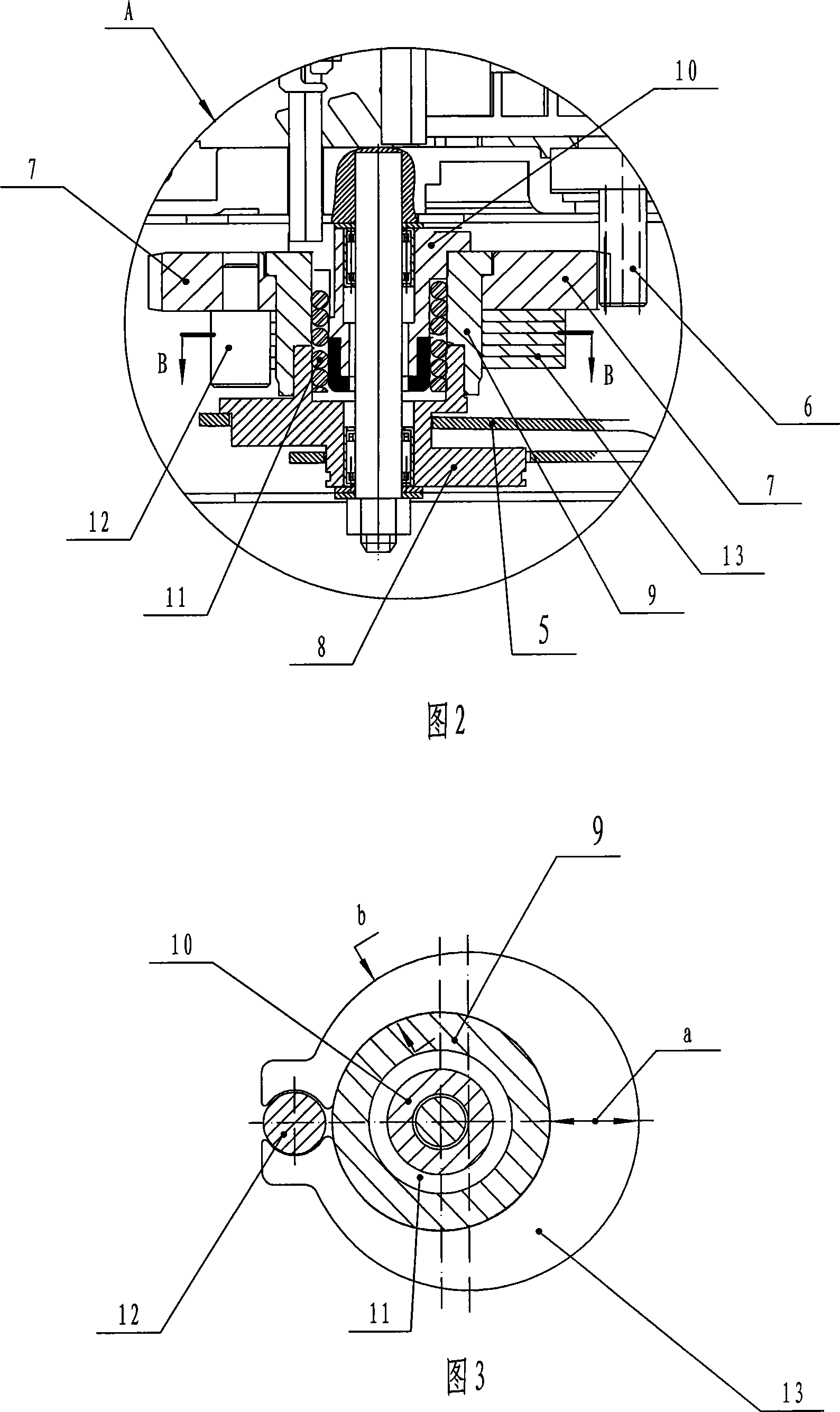
[0017] As shown in FIGS. 1 , 2 and 3 , the pruning machine of the present invention mainly includes a casing 1 , a motor 2 , a transmission mechanism, a main handle 3 , an auxiliary handle 4 and a blade 5 . The transmission mechanism is composed of an input gear 6, an output gear 7 and an eccentric block assembly; the eccentric block assembly includes an eccentric block 8 that causes the blade 5 to reciprocate due to rotational motion, an eccentric block outer cover 9, and an eccentric block outer cover 9. brake block 10 and torsion spring 11. The eccentric block casing 9 is integrated with the eccentric block 8 through the brake block 10 and the torsion spring 11; On the circular step, the other end is tightly fitted on the outer circular step of the brake block 10; the input gear 6 and the output gear 7 mesh with each other.

[0018] The above st...


PUM


Abstract

The present invention discloses a pruning machine. Its transmission mechanism is composed of input gear, output gear and eccentric block component. The described eccentric block component includes eccentric block, eccentric block case shell, brake block mounted in the eccentric block case shell and torsion spring. The eccentric block case shell is connected together with said eccentric block and formed into one body by means of brake block and torsion spring. Besides, said invention also provides the working principle of said pruning machine, and also provides its concrete operation method.

Description

Technical field: [0001] The invention relates to a cutting tool dedicated to gardening, in particular to a pruning machine capable of pruning and trimming branches, shrubs or hedges. Background technique: [0002] The pruning machine of prior art generally comprises main components such as casing, motor, transmission mechanism, main handle, auxiliary handle and the upper and lower blades that are connected with transmission mechanism; The output shaft drives the upper and lower blades outside the casing to move through the transmission mechanism. The transmission mechanism is generally composed of an input gear, an output gear and an eccentric block assembly; the eccentric block assembly includes an eccentric block that causes the blade to reciprocate due to rotational motion, and a brake block and a torsion spring located in the outer casing of the eccentric block; the torsion spring is tightly It is set in the inner hole of the eccentric block outer casing, that is, the o...

Claims


Application Information

Patent Timeline
Patent Type & Authority Applications(China)
IPC IPC(8): A01G3/00A01G3/08
Inventor 李志军
Owner NINGBO ENERGY POWER TOOLS
Why Eureka
Try Eureka