Thin film extraction tank transmission device

A transmission device and extraction tank technology, which is applied in the field of film extraction tank transmission devices, can solve the problems of lengthening of the extraction tank, expensive perfluoroether, leakage, leakage, etc., and achieve the effect of simple structure, convenient maintenance, and avoiding vibration transmission

Active Publication Date: 2013-02-06
QINGDAO ZHONGKEHUALIAN ADVANCED MATERIAL CO LTD
View PDF9 Cites 4 Cited by
  • Summary
  • Abstract
  • Description
  • Claims
  • Application Information

AI Technical Summary

Problems solved by technology

[0002] The extraction tank is the key equipment for film manufacturing. The existing extraction tank transmission basically uses the upper row of rollers as the driving shaft, the lower row of rollers as the passive shaft, and the upper row of rollers is not soaked in the extraction solution. The main problems are as follows There are two problems: one is that in order to meet the extraction time, the length of the extraction tank needs to be lengthened, which leads to a series of problems such as an increase in fixed investment
The second is that the lower row of rollers adopts passive rollers. During the extraction process, the diaphragm is subjected to an upward pull, which causes the microscopic deformation of the diaphragm’s pores, which affects the performance of the final product of the diaphragm.
Even though some equipment currently has the upper and lower rows of rollers as driving shafts, the axial sealing effect is not good. Traditional sealing methods such as skeleton oil seals and O-ring seals are used, which are prone to leakage, leakage, etc. in the normal production process. Phenomenon, not conducive to environmental protection
In addition, the selected extractant-resistant material (perfluoroether) is relatively expensive, and it is very difficult to replace, and the liquid in the entire tank needs to be drained

Method used


Image

  • Thin film extraction tank transmission device
  • Thin film extraction tank transmission device
  • Thin film extraction tank transmission device

Examples


Embodiment Construction

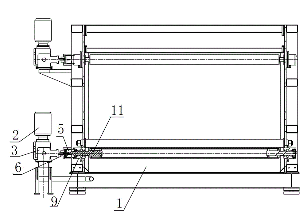
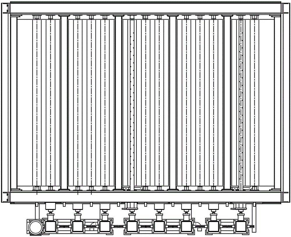
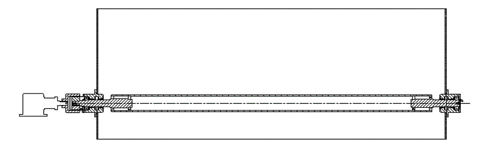
[0022] In conjunction with the accompanying drawings, a transmission device for a thin film extraction tank includes an extraction tank 1. In the extraction tank 1, an upper row of roller shafts and a lower row of roller shafts are alternately arranged. The upper row of roller shafts and the lower row of roller shafts pass through a motor and a reducer respectively. 2. The T-type commutator 3 and the magnetic driver drive the rotation. The T-shaped commutator 3 is fixed on the commutator bracket 4 . The magnetic drive includes an inner magnetic drive 5 and an outer magnetic drive 6, the outer magnetic drive 6 is installed on the T-shaped commutator 3, the T-shaped commutator 3 is connected with the motor and the reducer 2, and the inner magnetic drive 5 is installed on the roller shaft output. The internal magnetic drive 5 is coated with stainless steel (FeNdB) to ensure resistance to methylene chloride. A spacer 7 is arranged between the inner magnetic drive 5 and the outer...


PUM


Abstract

The invention discloses a thin film extraction tank transmission device which comprises an extraction tank, wherein an upper row of roll shaft and a lower row of roll shaft are arranged in the extraction tank in a staggered manner; each row of roll shaft is driven to rotate through a motor and reducer, a T-shaped reverser and magnetic drivers; the magnetic drivers are an inner magnetic driver and an outer magnetic driver; the outer magnetic driver is mounted on the T-shaped reverser; the T-shaped reverser is in transmission connection with the motor and reducer; the inner magnetic driver is mounted on the output end of the row of roll shaft; and a spacer sleeve is arranged between the inner magnetic driver and the outer magnetic driver, and is fixed on the tank body of the extraction tank. As the magnetic drivers are adopted for transmitting power, and the upper row of roll shaft and the lower row of roll shaft are both driving rolls and rotate synchronously, microscopic deformation in diaphragm pore-forming is avoided during a conveying process, and the performance of a diaphragm is guaranteed; and as the magnetic drivers are adopted, the sealing effect is good, and phenomena such as evaporating, emitting, dripping and leaking of an extracting agent can be avoided during the normal production process.

Description

technical field [0001] The invention relates to a film extraction tank device, in particular to a film extraction tank transmission device. Background technique [0002] The extraction tank is the key equipment for film manufacturing. The existing extraction tank transmission basically uses the upper row of rollers as the driving shaft, the lower row of rollers as the passive shaft, and the upper row of rollers is not soaked in the extraction solution. The main problems are as follows There are two problems: one is that in order to meet the extraction time, the length of the extraction tank needs to be lengthened, which leads to a series of problems such as an increase in fixed investment. The second is that the lower row of rollers adopts passive rollers. During the extraction process, the diaphragm is subjected to an upward pulling force, which causes the microscopic deformation of the diaphragm’s pores, which affects the performance of the final product of the diaphragm. ...

Claims


Application Information

Patent Timeline
Patent Type & Authority Applications(China)
IPC IPC(8): B01D11/00
Inventor 韩向前殷振胜聂海东郅立鹏陈继朝
Owner QINGDAO ZHONGKEHUALIAN ADVANCED MATERIAL CO LTD
Why Eureka
Try Eureka