Injection mouth and vertical plastic injection forming machine injection head

An injection molding machine and injection head technology, applied in the field of plastic injection molding machinery design, can solve the problems of material leakage, economic loss of the owner, leakage of fluid materials, etc., and achieve the effect of preventing material leakage and facilitating the injection volume.

Inactive Publication Date: 2008-01-16
金孝禹
View PDF0 Cites 4 Cited by
  • Summary
  • Abstract
  • Description
  • Claims
  • Application Information

AI Technical Summary

Problems solved by technology

[0005] The disadvantage of the traditional vertical plastic injection molding machine is that in the normal working process, some plasticized fluid ma

Method used


Image

  • Injection mouth and vertical plastic injection forming machine injection head
  • Injection mouth and vertical plastic injection forming machine injection head
  • Injection mouth and vertical plastic injection forming machine injection head

Examples


Embodiment 1

[0030] (Example 1, injection nozzle)

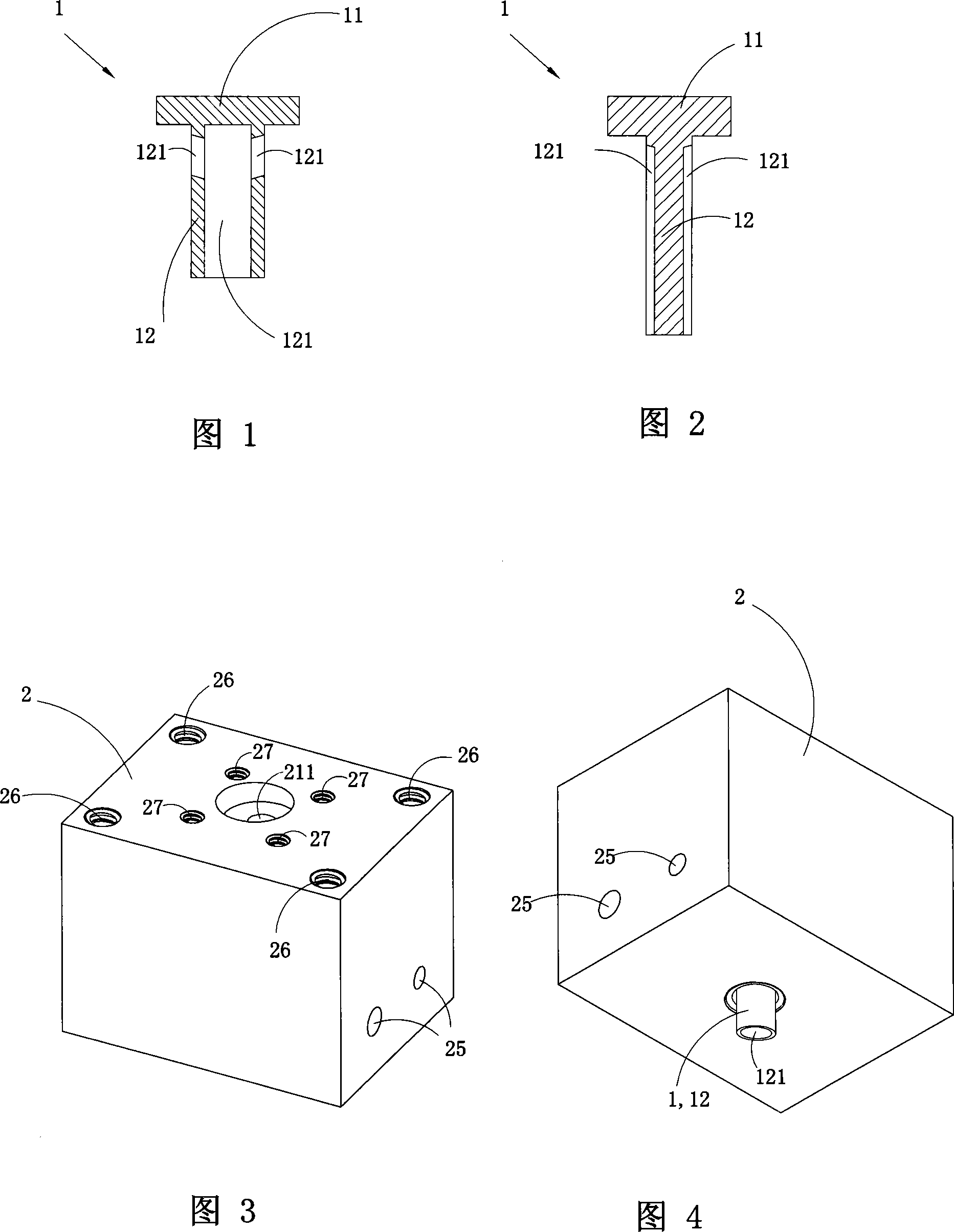
[0031] Fig. 1 is a cross-sectional schematic view of the first structure of the injection nozzle of the present invention, showing the first embodiment of the injection nozzle of the present invention.

[0032] See Fig. 1, the basic shape of this kind of injection nozzle is a T shape with a large top and a small bottom, the upper part is a sealing part 11, and the lower part is a discharge part 12; the discharge part 12 is provided with a discharge channel 121. The discharge channel 121 in the injection nozzle 1 is a Y-shaped channel arranged vertically on the discharge part 12, and the vertical part of the lower part of the Y-shaped channel is arranged at the center of the discharge part 12. In the round hole, the two branches on the upper part of the Y-shaped channel pass through the discharge part 12 .

Embodiment 2

[0033] (Example 2, injection nozzle)

[0034] Fig. 2 is a schematic cross-sectional view of the second structure of the injection nozzle of the present invention, showing the second embodiment of the injection nozzle of the present invention.

[0035] See Fig. 2, this embodiment is basically the same as Embodiment 1, the difference is: the shape and position of the discharge passage 121 of the discharge part 12 are different, and the discharge passage 121 of the present embodiment is arranged along the vertical direction Grooves on the outer surface of the discharge part 12.

Embodiment 3

[0036] (Embodiment 3, injection head)

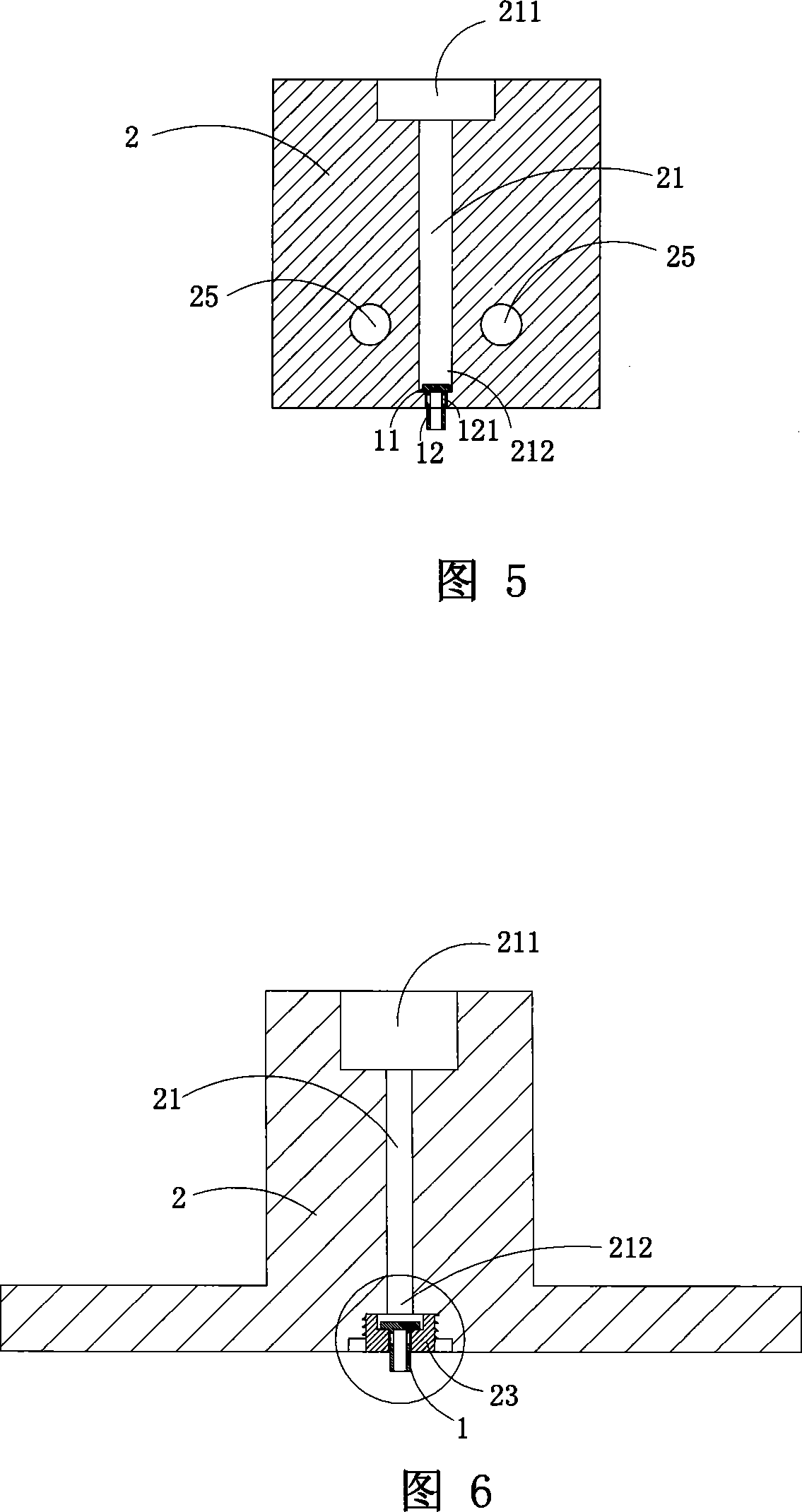
[0037] Figures 3 to 5 show the first embodiment of the injection head of the present invention, wherein Figure 3 is a schematic perspective view of the first structure of the injection head of the present invention. Fig. 4 is a schematic perspective view of the three-dimensional structure of the injection head shown in Fig. 3 viewed from another angle. Fig. 5 is a cross-sectional view of the injection head shown in Fig. 3 .

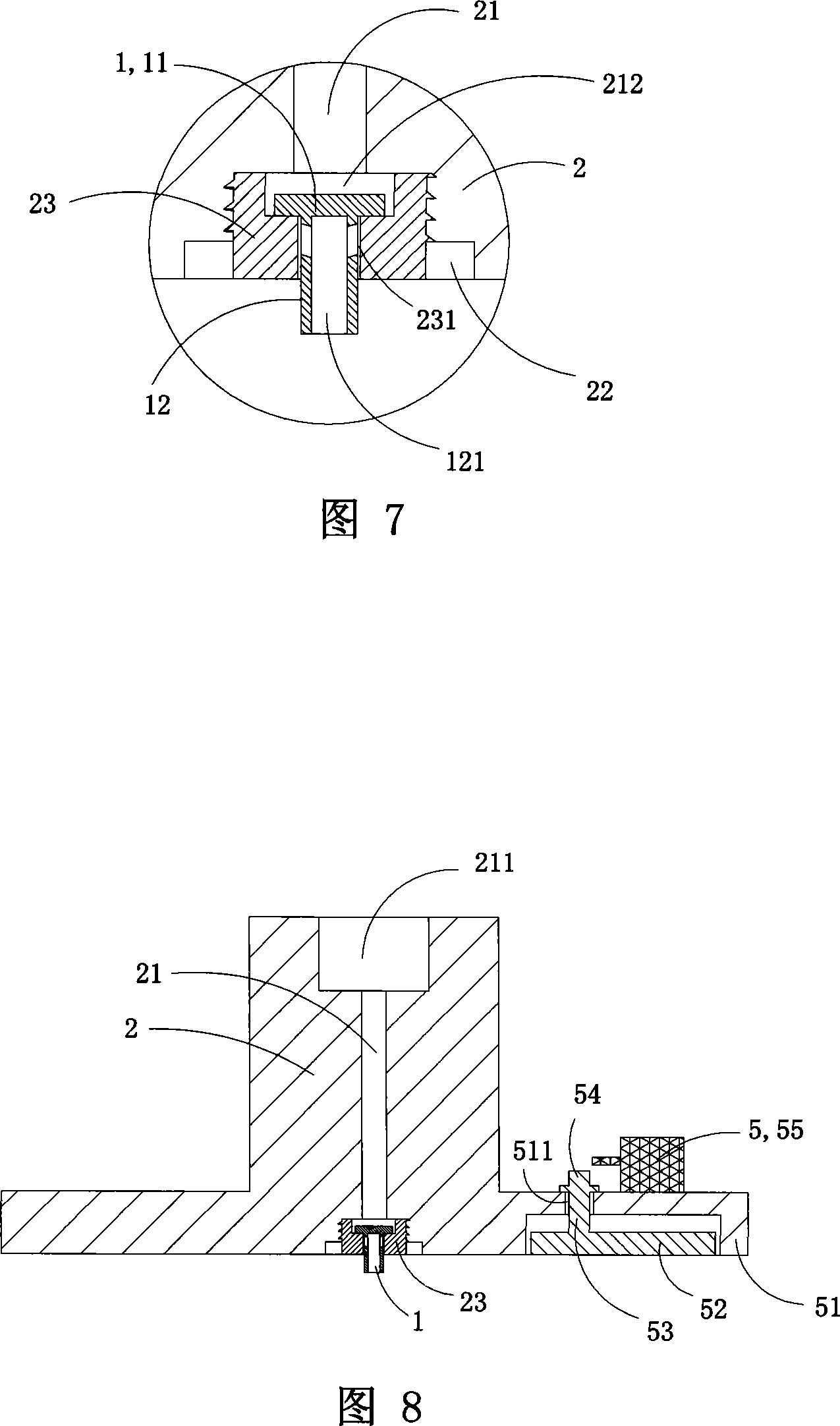
[0038] This embodiment is an injection head for a vertical plastic injection molding machine, the injection head body 2 is provided with a material injection channel 21, the material inlet 211 and the material injection port 212 of the injection channel 21; The feed port 211 of the injection head body is located at the top of the injection head body 2 , and the material injection port 212 is located at the bottom end of the injection head body 2 .

[0039] The injection nozzle 1 that can inject material and preven...


PUM


Abstract

The invention discloses an injection tooth and an injection head of an upright plastic injection molding machine with a said injection tooth. The injection tooth takes the shape of T, with the upper part being a sealing unit and the lower part being a discharge unit which is provided with a discharge channel. The body of the injection head is provided with an injection pore canal, a feeding port and an injection port for the injection pore canal; the injection tooth which can both inject materials and prevent the materials from leaking, is inserted into the feeding port; the injection tooth takes the shape of T, with the upper part being a sealing unit and the lower part being a discharge unit; the sealing unit can cover and seal up the feeding port; the discharge unit is provided with a discharge channel and the bottom of the discharge unit stretches out of the feeding port, that means, the bottom of the discharge unit is lower than the lower surface of the body of the injection head. The injection tooth and the injection head of the invention can prevent the materials from leaking from the injection head.

Description

technical field [0001] The invention belongs to the field of plastic injection molding machinery design, in particular to an injection nozzle and an injection head of a vertical plastic injection molding machine using the injection nozzle. Background technique [0002] Disc-type plastic injection molding machine is a kind of equipment specially used for manufacturing plastic soles. The discs used are often equipped with multiple sole molds of the same style and different sizes at the same time. Therefore, it is necessary to set the molds on the turntable for plastic The injection molding machine injects and molds molds with the same style and different code numbers in stages, and facilitates the process of opening the mold and taking out the molded sole. [0003] Disc plastic injection molding machines are generally divided into horizontal plastic injection molding machines and vertical plastic injection molding machines due to the different selection of pre-molding mechanis...

Claims


Application Information

Patent Timeline
IPC IPC(8): B29C45/20B29C45/23B29C45/74B29C45/17
Inventor 金孝禹
Owner 金孝禹
Why Eureka
Try Eureka