Movable contact of circuit breaker

A circuit breaker and moving contact technology, applied in the direction of circuit breaker contacts, circuit breaker components, contacts, etc., can solve the problems that have not been reported in the literature successfully, and achieve the improvement of short-term withstand current value and overall Effective volume control to ensure the effect of miniaturization

Active Publication Date: 2008-01-16
CHANGSHU SWITCHGEAR MFG CO LTD (FORMER CHANGSHU SWITCHGEAR PLANT)
View PDF0 Cites 21 Cited by
  • Summary
  • Abstract
  • Description
  • Claims
  • Application Information

AI Technical Summary

Problems solved by technology

[0004] Although the industry has always been looking for a balance between ensuring the contact effect of the dynamic and static contacts and not

Method used


Image

  • Movable contact of circuit breaker
  • Movable contact of circuit breaker
  • Movable contact of circuit breaker

Examples


Embodiment 1

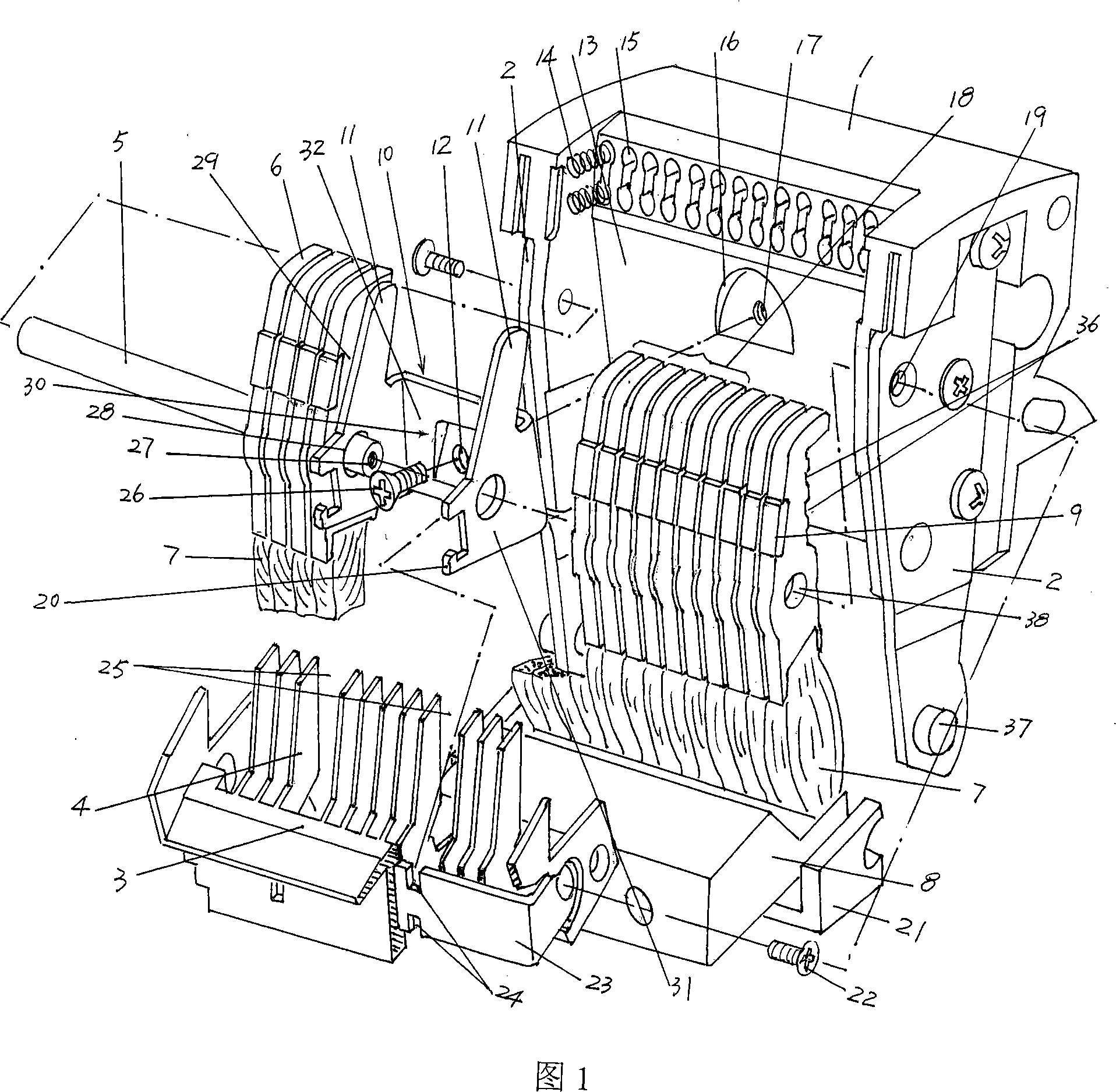
[0023] Please refer to Fig. 1 in detail, which provides an insulating support 1 whose material is preferably plastic. The side of the insulating support 1 facing a group of parallel conductors 6 is processed into an insulating slope 13, and the upper area of ​​the insulating slope 13 is arranged with a set of The number of conductors of the parallel conductor 6 is equivalent to the spring hole 15 corresponding to the position. The spring hole 15 can also be called a spring seat. One end of the spring 14 is inserted in each spring hole 15, and the other end of the spring 14 is resisted on the parallel conductor 6. The upper spring is accommodated on the concave cavity 36 . In the middle part of the insulating support 1, more specifically, in the middle part of the upper part of the insulating slope 13, a concave cavity 16 for fixing the fixing bracket 10, which will be described in detail below, is processed, and the central processing of the concave cavity 16 There are threade...

Embodiment 2

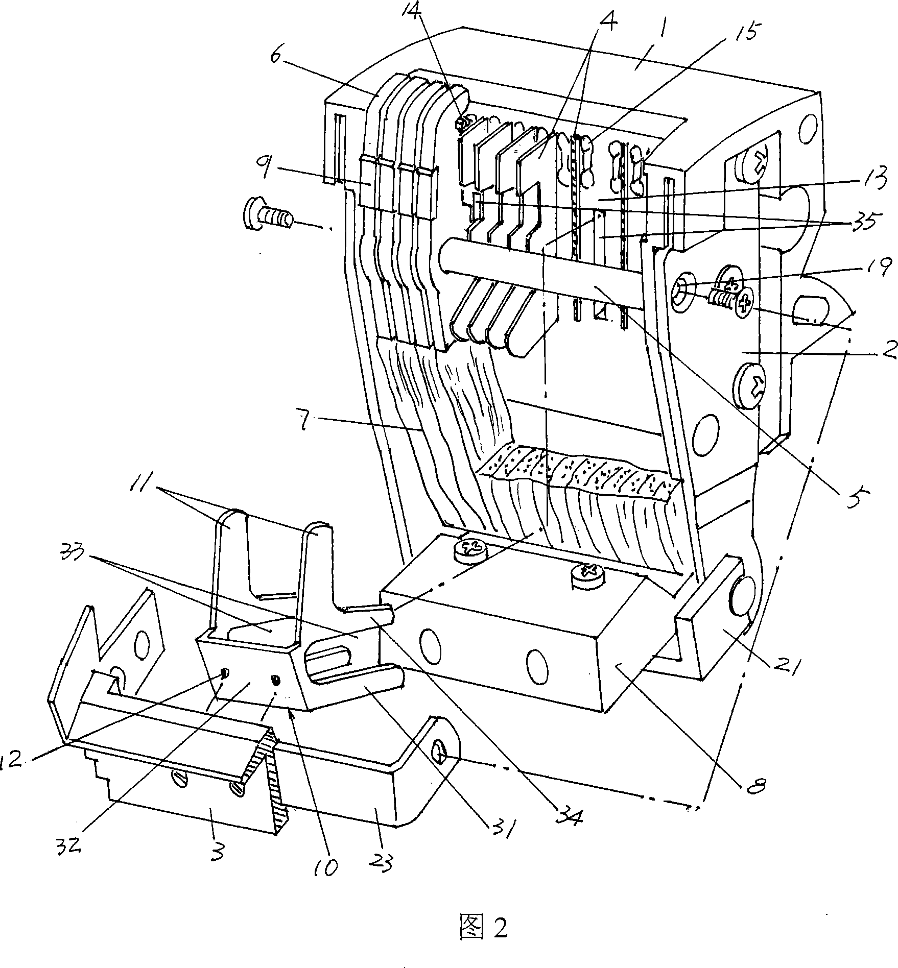
[0028] Please refer to FIG. 2 . As another specific embodiment, a set of grid pieces 4 is extended on the insulating slope 13 of the insulating support 1 . On a pair of side walls 31 of the parallel conductor connection cavity 30 of the fixed bracket 10, slots 33 corresponding to each other are provided respectively. It can be accompanied by the parallel conductor 6 without causing the rotary support shaft 5 to pass through the pair of fixed plates 2 to form an obstacle, so the slot 33 spans the rotary support shaft 5 . The second pins 34 narrowly extend in the direction of the pair of side walls 31 facing the insulating support 1. In order to compensate for the pair of second pins 34, a pair of second pin receiving grooves are opened on the insulating slope 13 of the insulating support 1. 35. The bottom wall of the parallel conductor receiving cavity 30 is fixed to the grid seat 3 by screws or other similar means, so as to ensure that a pair of side walls 31 of the fixing br...


PUM


Abstract

A moving contact on circuit breakers belongs to the technical field of low-voltage electric appliance, and includes: an insulated support, a pair of fixing plate, a grid base, a group of grids, a rotary supporting shaft, a group of parallel conductors, a flexible conductive connection wire, and a conducting block. The invention is characterized in that the invention includes a fixing support, which is arranged on the insulating support and grid base along with a group of parallel conductors; one of the parallel conductors should be in the fixing support and at the same position as other conductors. The group of grids is arranged on the grid base or the insulated support. The invention can lower the temperature rise of the moving contact and static contact in short circuit, lift the short-time withstand current value of the breaker; keep the small size of moving contact so as to control the overall cubage of the breaker; and the fixing support is simple in structure and convenient in installation, thus being economical and practical industriously.

Description

technical field [0001] The invention relates to a moving contact of a circuit breaker, which is arranged in the moving contact chamber of the base of the circuit breaker, cooperates with the static contact to make and break the circuit, and belongs to the technical field of low-voltage electrical appliances. Background technique [0002] As is well known in the industry, in the actual use of circuit breakers, the self-resistance of the conductors of the circuit breaker and the contact resistance between the moving and static contacts play an important role in the short-term short-term withstand performance of the circuit breaker. For example, the greater the self-resistance of the conductor or the contact resistance between the moving and static contacts, the easier it is to cause the heat generation of the circuit breaker to increase when it is subjected to a short-circuit current, causing the contact of the moving and static contacts (moving contact The movable contact on ...

Claims


Application Information

Patent Timeline
IPC IPC(8): H01H71/00H01H73/04H01H1/14H01H1/22H01H1/32
CPCH01H1/226
Inventor 周敏琛管瑞良俞晓峰
Owner CHANGSHU SWITCHGEAR MFG CO LTD (FORMER CHANGSHU SWITCHGEAR PLANT)
Why Eureka
Try Eureka