Pressing mechine, pressing method, and punched article

A processing device, pressure technology, applied in the field of punching products, can solve the problem of size increase

Inactive Publication Date: 2008-01-16
AISIN AW CO LTD
View PDF2 Cites 22 Cited by
  • Summary
  • Abstract
  • Description
  • Claims
  • Application Information

AI Technical Summary

Problems solved by technology

Moreover, the second conventional device also has the problem that since a third processing unit for trimming the side wall surface of the blank hole (third process) is also provided, compared with the first conventional device, The size of the device structure is increased by a corresponding amount

Method used


Image

  • Pressing mechine, pressing method, and punched article
  • Pressing mechine, pressing method, and punched article
  • Pressing mechine, pressing method, and punched article

Examples


no. 1 example

[0055] Next, with reference to FIGS. 1 to 12 , the first embodiment of the present invention will be described. The first embodiment is a press working device and a press working method used when punching out a punching body from a thicker plate.

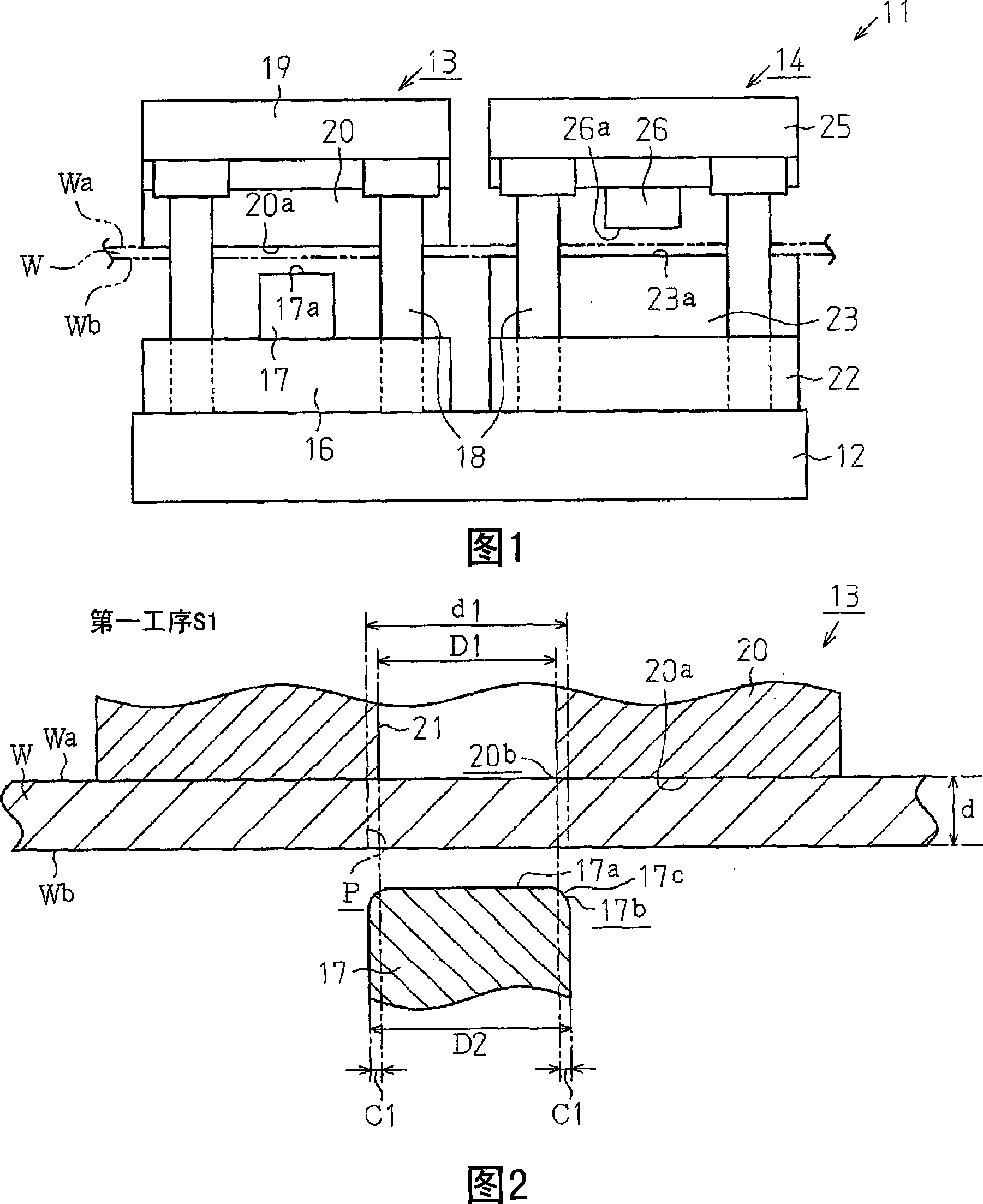
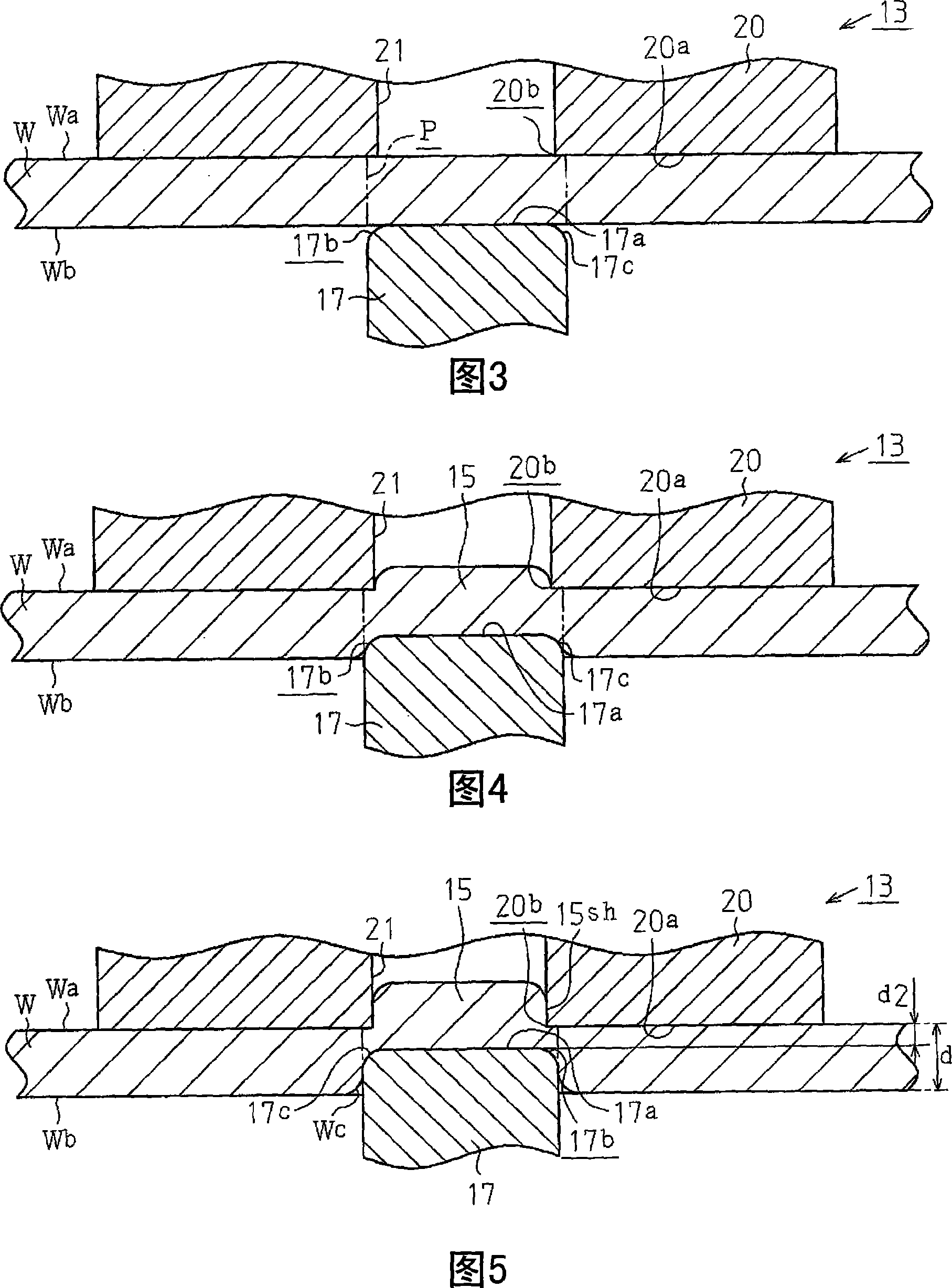
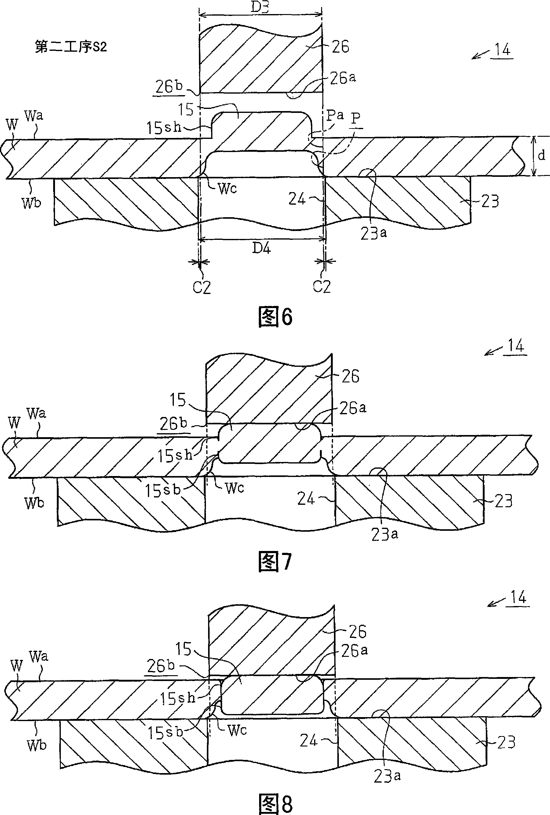
[0056] As shown in FIG. 1 , in the press working device 11 of this embodiment, a first processing unit 13 and a second processing unit 14 are arranged side by side on a substrate 12 . In addition, the press processing device 11 uses each processing unit 13, 14 to form a through hole P (see FIG. 12 ) having a given shape (in this embodiment, the cross section is substantially circular) in the sheet W, and the sheet W (for example: A hot-rolled steel sheet (JISS PH440) for automobile structures is formed of a metallic material. That is, in the first processing unit 13, as shown in FIG. It has a shape that protrudes upward from the plate W. In the second processing unit 14, as shown in FIG. A through hole P is formed at the portion ...

no. 2 example

[0087] Next, a second embodiment of the present invention will be described based on FIGS. 13 to 19 . Furthermore, the second embodiment is slightly different from the first embodiment in terms of processing units. Therefore, in the following description, parts different from the first embodiment will be mainly described; members and structures that are the same as or corresponding to the first embodiment will be given the same reference numerals, and repeated description will be omitted.

[0088] The press working device 11 of this embodiment has a first working unit 13 and a second working unit 14 . In the first processing unit 13 , a first punch 17 is fixedly mounted on the lower die 16 , and a first die 20 corresponding to the first punch 17 is fixedly mounted on the lower surface side of the upper die 19 . The first punch 17 is formed in a substantially cylindrical shape, and also has a diameter dimension D2 of, for example, 30 mm.

[0089] In addition, as shown in FIG....

no. 3 example

[0107] Next, a third embodiment of the present invention will be described based on FIG. 20 . Furthermore, the third embodiment is slightly different from the first embodiment in terms of processing units. Therefore, the following description will mainly describe parts that are different from the first embodiment; members and structures that are the same as or corresponding to the first embodiment will be given the same reference numerals, and repeated description will be omitted.

[0108] The press working device 11 of the present embodiment has a first working unit 13 and a second working unit 14, and forms a steel plate having a given shape (in this embodiment, In this example, the through-hole P having a substantially circular cross-section), the plate W is formed of a metal material having a predetermined thickness (for example: 3mm). In this first processing unit 13 , a first punch 17 is fixedly mounted on the lower die 16 , and a first die 20 corresponding to the first...


PUM


Abstract

A pressing machine, a pressing method and a punched article in which the punching surface along the punching direction can be formed like a sheared surface at a part where a body to be punched is punched while suppressing increase in size of the machine itself and in the number of punching steps, and generation of burrs in a plate material can be suppressed. The press is provided with a first press unit (13) and a second press unit (14) wherein the first press unit (13) performs a first step for forming a protruding half die cutting portion (15) at a part of the plate material W where a through hole P is formed. The second press unit (14) performs a second step (S2) for punching the half die cutting portion (15) from the plate material W by means of a second punch (26) and a second die (23). When the body to be punched is punched from the plate material W in the second step (S2), side wall face Pa at a part of the plate material W where the body to be punched is punched is subjected to shaving.

Description

technical field [0001] The present invention relates to a press working device for punching a relatively thick plate, such as an element of a belt for a continuously variable transmission, a press working method, and a punched product manufactured by the press working device. ) and raw materials for press-formed parts of automatic transmissions, etc. Background technique [0002] Conventionally, as such a press working device, for example, a press working device (press molding device for piercing) described in Patent Document 1 has been proposed. This press working device (hereinafter referred to as "first conventional device") has two working units (a first working unit and a second working unit). Each processing unit is provided with a punch and a die, respectively. And, in the first processing unit, by relatively moving the punching machine and the die, forming a through hole with a direction toward the A half-cut part of the shape protruding from the mold side. That ...

Claims


Application Information

Patent Timeline
Patent Type & Authority Applications(China)
IPC IPC(8): B21D28/16B21D28/14B21D28/10
CPCB21D28/16
Inventor 谷口孝男池田重晴日高实加藤拓也上野三夫
Owner AISIN AW CO LTD
Why Eureka
Try Eureka