
Electrolytic cell with enlarged active membrane surface

A technology of electrolytic cell and diaphragm, which is applied in the field of electrolytic cell and can solve problems such as short circuit of diaphragm

Inactive Publication Date: 2008-01-16
UHDENORA
View PDF6 Cites 0 Cited by
  • Summary
  • Abstract
  • Description
  • Claims
  • Application Information

AI Technical Summary

Problems solved by technology

If the spacer element is made of conductive material, short circuits can be caused in the diaphragm under the influence of mechanical loads and under the influence of reducing the thickness of the diaphragm

Method used


Image

  • Electrolytic cell with enlarged active membrane surface
  • Electrolytic cell with enlarged active membrane surface
  • Electrolytic cell with enlarged active membrane surface

Examples


Embodiment Construction

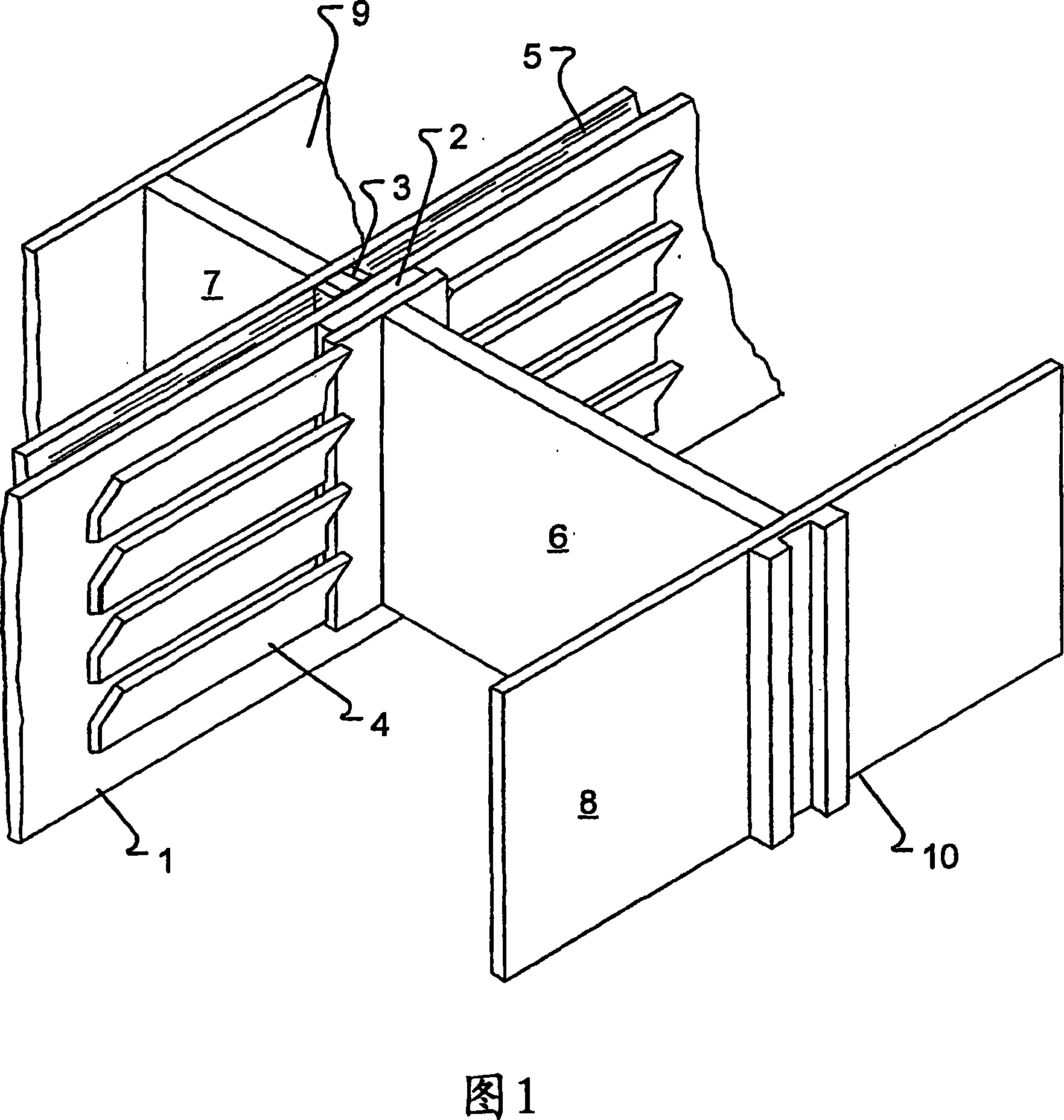
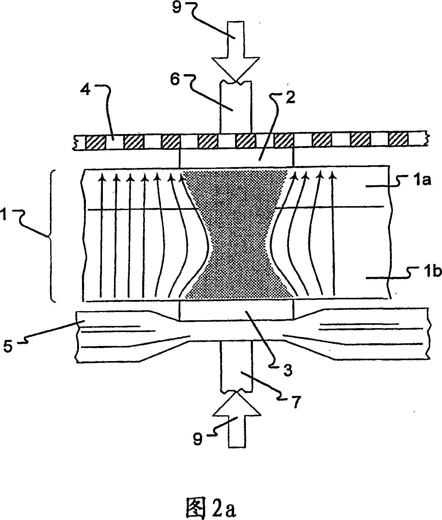
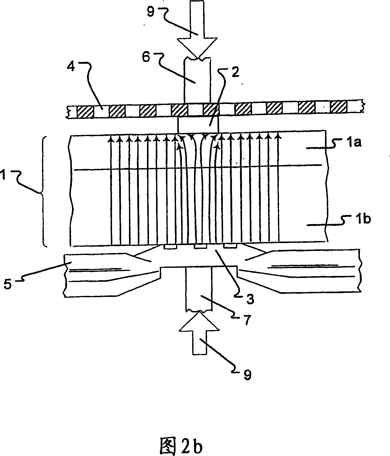
[0017] Figure 1 shows some internal parts in a perspective view of an electrolytic cell according to the invention. Diaphragm 1 is clamped between spacers 2 and 3 in direct contact with it. The anode 4 is pressed firmly against the anode 4 by the spacer element 2 welded on the back side to the elongated strip 6 . This strip is welded at its corners to the housing wall 8 of the half-container. On the half-container shell wall 8, along the height of the elongated strip 6, a contact strip 10 is arranged, in this case making the contact strip 10 groove-shaped and accommodating the contact strip adjoining the electrolytic cell (not shown in the figure) .

[0018] The structure of the cathode side is similar, so that the cathode 5 is in direct contact with the spacer element 3 welded to the elongated strip 7 on the rear side. The spacer element 3 is provided with openings as shown in detail in FIG. 3 . The elongated strip 7 is welded to the housing half wall 8 in its corners.

...


PUM


Abstract

The invention relates to an electrolytic cell for the production of chlorine from an aqueous alkali halide solution, which mainly consists of two semi-shells, an anode, a cathode and an ion exchange membrane arranged between the electrodes. Spacer elements are arranged between the ion-exchange membrane and the electrodes for fixing the membrane in position and distributing the compressive forces, made of electrically conductive and corrosion-resistant material on at least one side of the membrane.

Description

technical field [0001] The present invention relates to an electrolytic cell for the generation of chlorine gas from aqueous alkaline halide solutions, essentially consisting of two half-container shells, an anode, a cathode and an ion exchange membrane (hereinafter referred to as "diaphragm"). The inside of each half-container shell is equipped with some thin strips made of conductive material that support each electrode and transmit the clamping force from the outside, and are installed between the ion exchange membrane and the electrode to fix the membrane in a suitable position. Position and distribute the mechanical force of the spacer element. A gasket is provided on at least one side of the ion exchange membrane and is made of a material that is both electrically conductive and corrosion resistant. Background technique [0002] Electrolyzers of the single cell type for generating halogen gases are known in the art. In a single cell type construction, up to 40 indivi...

Claims


Application Information

Patent Timeline
IPC IPC(8): C25B9/08C25B9/19C25B9/23
CPCC25B9/10C25B9/045C25B9/08C25B9/66C25B9/23C25B9/19C25B1/04C25B11/046
Inventor 罗兰·贝克曼卡尔-海因茨·杜勒兰道夫·基弗彼得·沃尔特林
Owner UHDENORA
Learn More