Image display device comprising an imaging matrix

一种图像显示装置、成像矩阵的技术,应用在图像通信、光学、仪器等方向,能够解决不适合等问题,达到大观看区域的效果

Inactive Publication Date: 2010-05-19
SEEREAL TECHNOLOGIES
View PDF10 Cites 0 Cited by
  • Summary
  • Abstract
  • Description
  • Claims
  • Application Information

AI Technical Summary

Problems solved by technology

Thereby above-mentioned solution method is not suitable for combining with the present application

Method used


Image

  • Image display device comprising an imaging matrix
  • Image display device comprising an imaging matrix
  • Image display device comprising an imaging matrix

Examples


Embodiment Construction

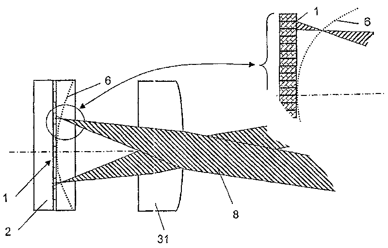
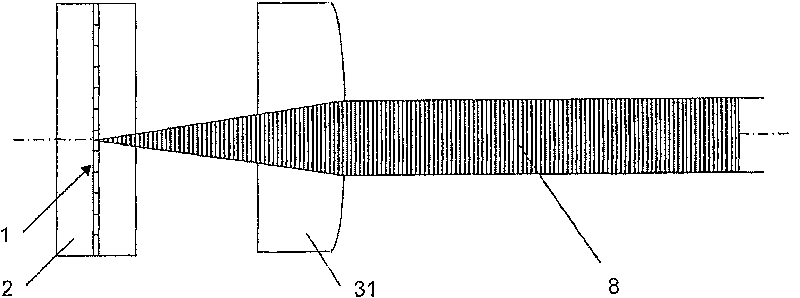
[0043] The effect of the correction matrix in projecting the point elements of the imaging matrix will now be described in detail according to the invention.

[0044] The imaging matrix consists of imaging elements, eg in the form of stripes or lenses. A lighting matrix consists of multiple lighting elements.

[0045] Figure 1 shows in simplified form the effect of midfield curvature on an autostereoscopic multi-user display. Field curvature represents the actual course of the back focus of oblique light rays, which occurs when the illumination elements are projected through the imaging elements of the imaging matrix. A lighting matrix (only partly shown in the figure), eg a shutter 2, contains a number of pixels 1 as lighting elements. Seen from the direction of light propagation, an imaging matrix in the form of a lens array with microlenses 31 in the shape of parallel stripes as image elements focusing the light at the eyes of the viewer is placed behind the illumination ...


PUM


Abstract

The invention relates to an image display device comprising an imaging matrix, which consists of imaging elements which are arranged in a lateral manner, for example, lenticulars or a lens array, anda plurality of point elements which are disposed on an object plane and which are formed from the imaging elements in an observation chamber. In order to reduce imaging errors resulting in the image field curvature of the individual imaging elements of a large observation angle, compensation by a correction matrix, which contains a plurality of optical correction elements, takes place. An opticalcorrection element is associated with each individual optical imaging element. Said invention can be used, for example, in image or video display devices, such as autostereoscopic displays, multi-user-displays with sweet-spot-units and multi-view-displays, in order to image illuminating elements. The invention also relates to displays comprising a sweet-spot-unit, which can be switched for one ormore observers into a two-dimensional mode and also in an autostereoscopic mode.

Description

technical field [0001] The invention relates to an image display device comprising an imaging matrix composed of laterally arranged imaging elements, such as a microlens array or a lens array. More specifically, the imaging element may be a spherical or aspheric lens element, a holographic optical element (HOE) or any other type of optical imaging element, which are combined or included with each other and arranged stacked in the direction of light propagation. Background technique [0002] The invention can be used, for example, in image lighting elements of image or video display devices such as autostereoscopic displays, multi-user displays with sweet spot units and multi-image displays. Furthermore, the invention can be advantageously used in large area display devices, such as billboards, typically for projected image elements. The application of heavy and bulky lenses is avoided by using the present invention. In this document reference is made to lighting components...

Claims


Application Information

Patent Timeline
Patent Type & Authority Patents(China)
IPC IPC(8): H04N13/00G02B30/27
CPCH04N13/0456H04N13/0404H04N13/0418G02B27/2214G02B27/2228H04N13/305H04N13/32H04N13/361G02B30/34G02B30/27G02B30/00
Inventor 阿明·史威特纳
Owner SEEREAL TECHNOLOGIES
Why Eureka
Try Eureka