Sheet hole punching apparatus and sheet hole punching method

A technology of perforating device and paper, applied in metal processing and other directions, can solve the problems of slowing down the perforation speed, increasing the load of the driving motor, and increasing the device of the driving part, so as to achieve the effect of fast perforation

Active Publication Date: 2008-01-23
成行有限公司
View PDF4 Cites 10 Cited by
  • Summary
  • Abstract
  • Description
  • Claims
  • Application Information

AI Technical Summary

Problems solved by technology

The structure of the old-fashioned punching parts only moves up and down in the direction of thrust. A lot of debris will accumulate under the perforation. , causing a malfunction
Moreover, the debris overflows to the perforation table and disperses into the paper or device, causing problems such as machine operation errors
[0008] Second, as mentioned above, the piercing structure utilizes the thrust movement in the vertical direction, and the huge shearing force will increase the load on the drive motor when piercing.
When punching plastic folders or thick cardboard, the load on the drive motor will increase. It is necessary to use a large-capacity motor or slow down the punching speed, etc., causing the need to increase the size of the drive unit and increase the cost.

Method used


Image

  • Sheet hole punching apparatus and sheet hole punching method
  • Sheet hole punching apparatus and sheet hole punching method
  • Sheet hole punching apparatus and sheet hole punching method

Examples


Embodiment 1

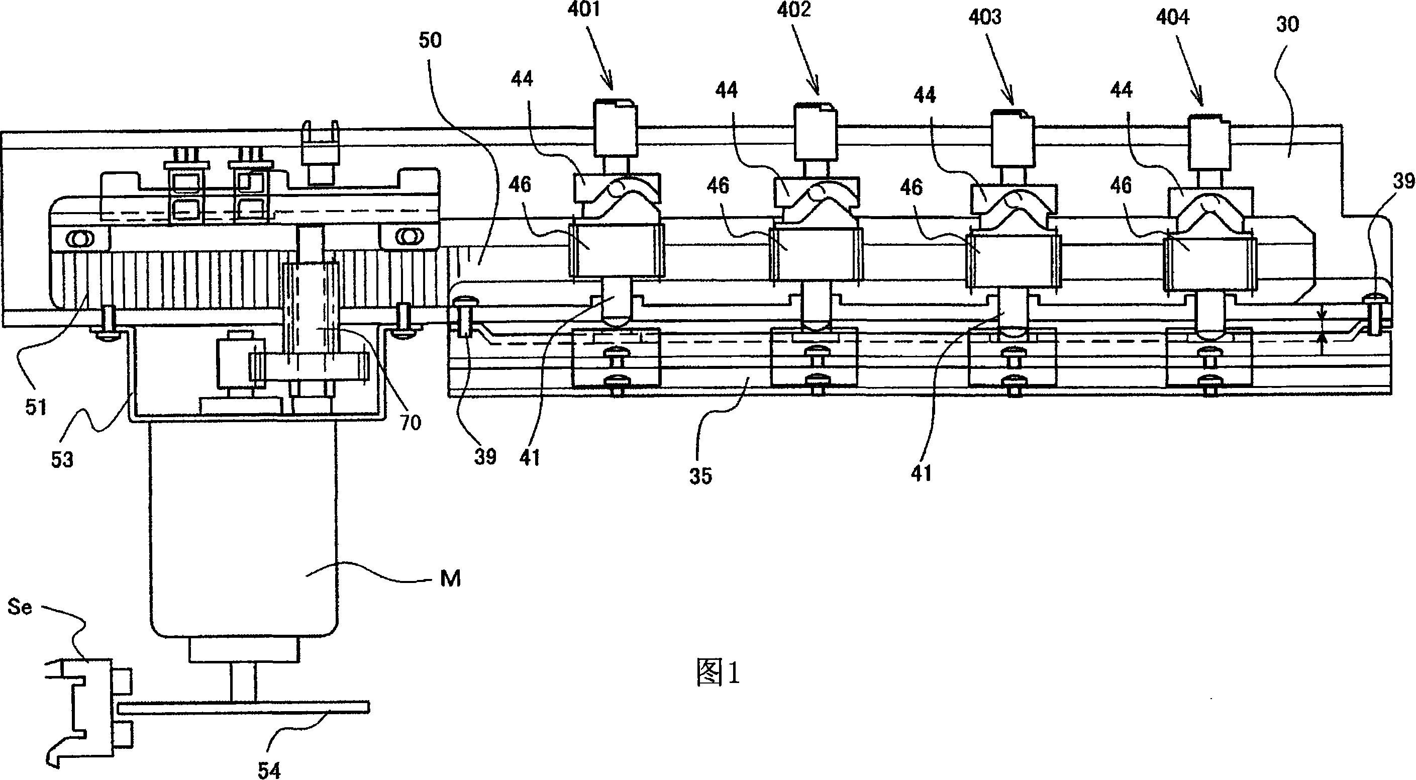
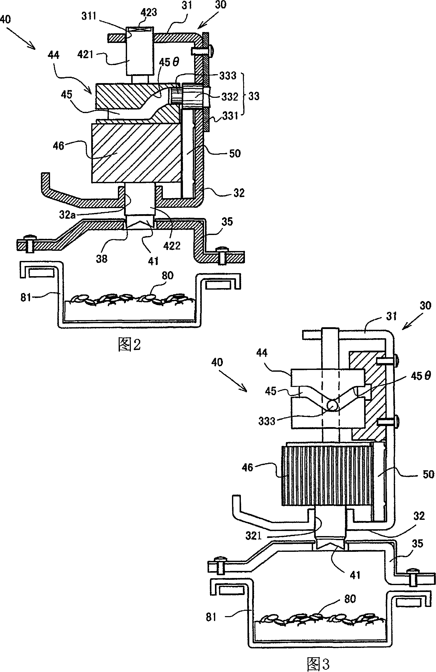
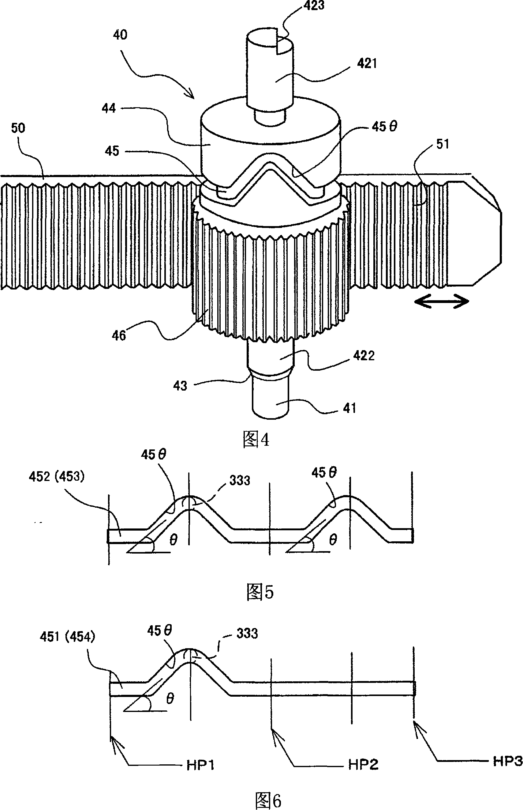
[0039] As shown in Figures 1 and 2, the perforating device of Embodiment 1 consists of an upper base 30 of a size corresponding to the perforated plate, a lower base 35 (also called an upper base 35) spaced between the upper base 30 and the perforated plate "Punching station"), the punching part 40 installed on the upper base 30 and the punching 38 arranged on the lower base 35, the driving motor M, the transmission mechanism and the cam mechanism are composed, and the above-mentioned punching part 40 is cylindrical , be provided with upper shaft 421 and lower shaft 422, and be provided with punching knife 41 at its front end namely lower end, punching part 40 is provided with 2 or 3 at intervals according to the specification (file hole specification) that upper abutment 30 decides Or 4 etc., the present embodiment is provided with 4: the first punching part 401 , the second punching part 402 , the third punching part 403 , the fourth punching part 404 .

[0040]The punching ...

Embodiment 2

[0065] Referring to Fig. 18 to Fig. 22, the second embodiment is described as follows.

[0066] The cylindrical cam 66 shown in FIGS. 18 and 19 is fixed on the upper base 30 , and a guide pin 65 combined with the cam groove 67 of the cylindrical cam 66 is provided on the side of the punching member 62 . In this embodiment, components having the same structure as those in Embodiment 1 are assigned the same numbers, and descriptions thereof are omitted.

[0067] The upper abutment 30 and the lower abutment 35 have the same composition as those in FIG. 1 , and both form a whole. The drive shaft 60 connected to the drive motor M is configured on the upper base 30. In addition, the same as the first embodiment, the upper base 30 is provided with an upper guide rail 31 and a lower guide rail 32, and its upper and lower guide holes 311, 321 It is automatically fitted up and down with the piercing member 40 . Four perforating members 40 are arranged, as shown in the figure, which is...

Embodiment 3

[0073] As shown in FIG. 23 , the difference between Embodiment 1 and Embodiment 2 in Embodiment 3 will be described below. The structure of the perforating member 62 is basically the same as that of the second embodiment, so the same numbers are used, and descriptions are omitted. The sliding cam 82 shown in FIG. 23 replaces the eccentric cam 61 in the second embodiment. The sliding cam 82 is connected with the driving motor, and a cam groove 83 with a V-shaped groove 831 is provided thereon. The cam groove 83 cooperates with the needle 832 on the top of the punching part 40, and the other structures of the punching part 62 are the same as those in the second embodiment.

[0074] As shown in Figure 23, when the sliding cam 82 is operated back and forth through a predetermined stroke, the pin 832 cooperating with the cam groove 83 moves from the upper apex of the V-shaped groove 831 to the lower apex, and moves to the thrust direction. The punching member 62 rotates along the ...


PUM


Abstract

The invention relates to a paper perforating device and a paper perforating method. A transmission mechanism is provided between the driving motor and the perforating part, and the rotational force of the driving motor is transmitted to the perforating part to provide the perforating part with a linear thrust or radial direction in the perforating direction. The rotation force of the piercing part is provided with a cam mechanism on the base frame supporting the piercing part and the piercing part to transform the transmission force of the transmission mechanism so that the piercing part moves up and down in the piercing direction and rotates at the same time, driving the motor forward or reverse Running in the direction, the perforating part moves up and down between the upper and lower vertices in the perforating direction and rotates at the same time. When moving from the upper apex to the lower apex, it rotates while piercing. The invention can obviously reduce the shearing force necessary for punching, realize the small capacity, small size and light weight of the driving motor, and can punch holes quickly without accumulation of debris under the punching parts.

Description

technical field [0001] The invention relates to a perforating method and a perforating device for perforating paper printed by image forming devices such as duplicating machines, printing machines and printers. Background technique [0002] Generally, there are two methods for punching holes on the paper that needs to be bound: the manual method of punching holes on several sheets of paper with the punching part of an office punching machine; the method of automatically punching holes after printing by printing machines, copiers, etc. The former is a device that clamps the paper, sets the cylindrical punching part in the frame to move up and down, pushes down the operating lever, and penetrates the paper. On the contrary, the latter is a device that fixes the printed paper at the predetermined processing position in order, presses down the motor that drives the punching part to punch holes, and is assembled with other devices for use. These devices perforate at 2, 3 or 4 pl...

Claims


Application Information

Patent Timeline
Patent Type & Authority Applications(China)
IPC IPC(8): B26F1/16B26D5/16B26D5/08B26D7/26
Inventor 马场健次
Owner 成行有限公司
Why Eureka
Try Eureka