
Control method and device for fuel injection

A technology of fuel injection and control device, applied in the direction of fuel injection control, fuel injection device, electrical control, etc., can solve problems such as fuel injection correction, and achieve the effect of correct fuel injection control

Inactive Publication Date: 2008-09-24
MIKUNI CORP
View PDF11 Cites 0 Cited by
  • Summary
  • Abstract
  • Description
  • Claims
  • Application Information

AI Technical Summary

Problems solved by technology

[0012] Compared with conventional fuel injection systems, this electromagnetic fuel injection system has the advantages of being smaller and lower in cost, but its fuel injection quantity will be affected by the coil current that drives the fuel injection solenoid. , there is a problem that only correcting the driving pulse width based on the power supply voltage of the above-mentioned battery cannot correct the fuel injection of the appropriate demand

Method used


Image

  • Control method and device for fuel injection
  • Control method and device for fuel injection
  • Control method and device for fuel injection

Examples


Embodiment approach

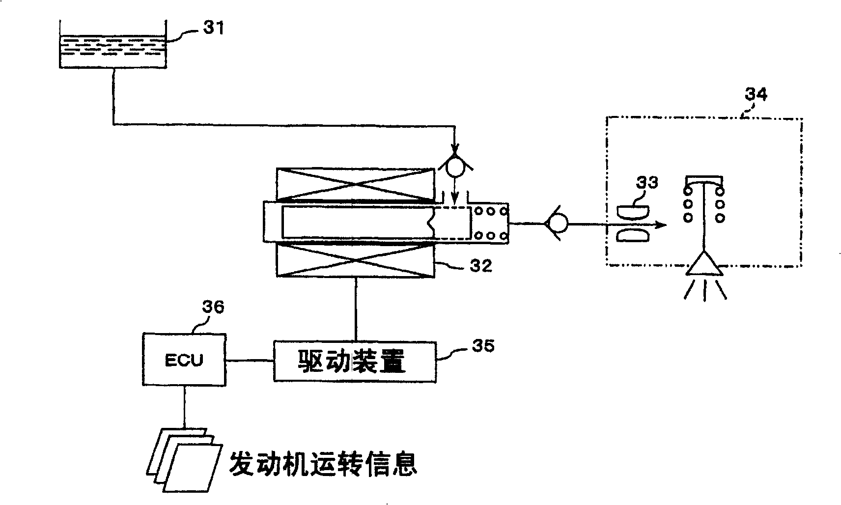
[0044] figure 1 An example of an overall schematic configuration of an electromagnetic fuel injection system including a fuel injection control device according to the present invention is shown.

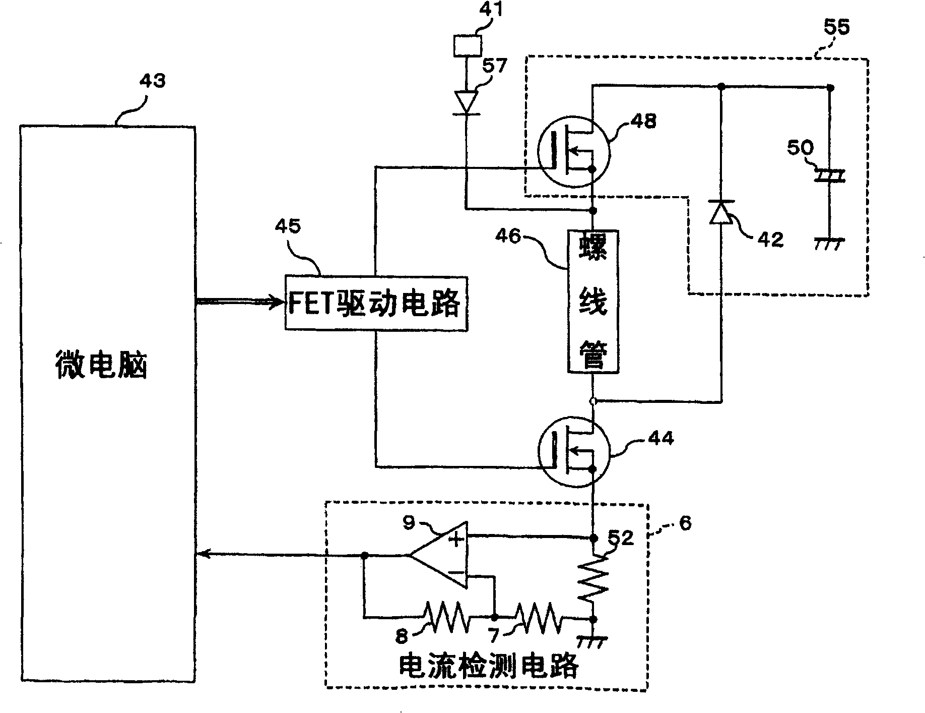
[0045] Such as figure 1 As shown, the basic structure of the electromagnetic fuel injection system includes: a plunger pump (plunger pump) 32 as an electromagnetically driven pump for pressure-feeding the fuel in the fuel tank 31; The inlet hole nozzle 33 of the orifice (orifice) portion of the fuel; the injection nozzle 34 that injects into the intake passage (of the engine) when the fuel passing through the inlet hole nozzle 33 is greater than a specified pressure; and the operating information of the engine and A control unit (ECU) 36 that outputs a control signal to the plunger pump 32 and the like based on a coil current flowing through a solenoid (fuel injection solenoid in this application) of the plunger pump 32 . Here, the control device in the fuel injection control de...

no. 2 Embodiment approach

[0065] Next, the fuel injection method according to the second embodiment of the present invention is applied to figure 1 The case of the electromagnetic fuel injection system of the structure shown is explained as an example. Since it overlaps with the previous example of the first embodiment, description of the configuration of the electromagnetic fuel injection system is omitted.

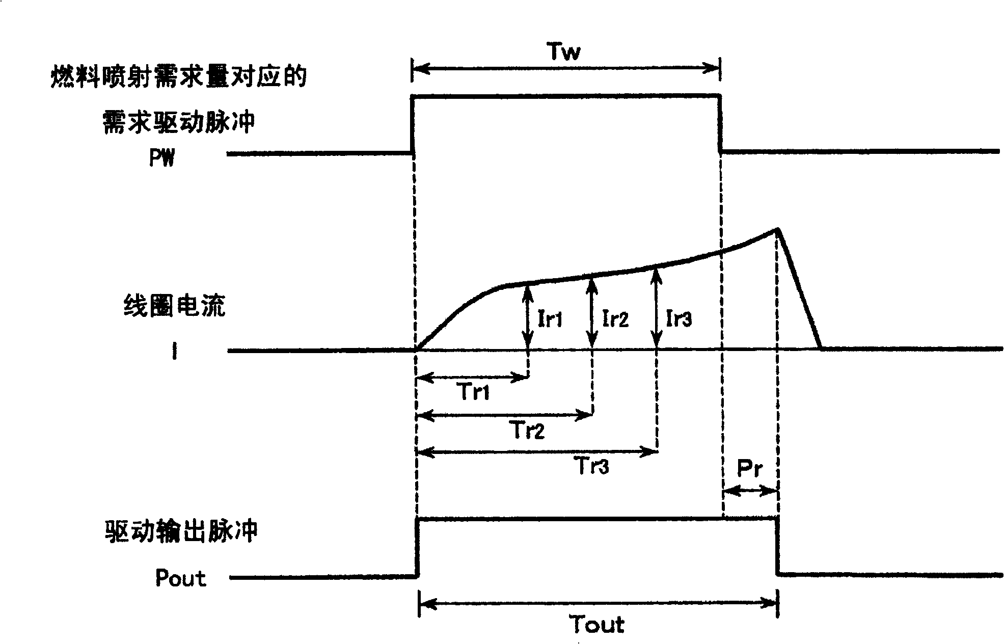
[0066] Here, in the present second embodiment, based on the slope correction value represented by the ratio of the increase amount of the fuel injection demand amount Qc to the increase amount of the solenoid drive output pulse width Tout, and the start of the solenoid drive to the start The corrected dead time between fuel injections is added to the product value of the required drive pulse corresponding to the fuel injection demand Qc and the slope correction value, and the corrected dead time is added to obtain the drive output pulse width Tout.

[0067] Figure 6 The relationship between t...


PUM


Abstract

A method and device for fuel injection, with which an adequate amount of fuel can be injected in accordance with a fuel injection amount required from an engine. A coil current is measured at one or plural time points at which a predetermined time after the start of fuel injection solenoid drive has been reached, and the time to stop the solenoid drive is corrected for adjustment based on the measured coil current value. The correction is made according to a correction value determined based on the measured coil current value and on the required fuel injection amount for the solenoid or according to a correction value selected from predetermined values for various combinations of measured coil current values and required fuel injection amounts, the selection being made in accordance with the combination of the measured coil current value and the required fuel injection amount.

Description

technical field [0001] The present invention relates to an electronically controlled fuel injection control method and its control device for supplying fuel to an engine etc., and in particular relates to a solenoid used for fuel injection that eliminates power supply voltage changes, temperature changes, etc. The fuel injection control method and control device for correctly injecting the fuel injection amount required by the engine under the influence of changes in the coil resistance value of the engine. Background technique [0002] For motor vehicle engines and the like including two-wheeled vehicles, the proper and proper supply of the fuel injection demand which changes momentarily is an extremely important factor affecting the performance of the internal combustion engine device. Therefore, conventionally, the fuel injection timing at the start of the engine has been corrected based on the temperature of the engine intake air and the battery voltage. (JP-A-58-28537 ...

Claims


Application Information

Patent Timeline
Patent Type & Authority Patents(China)
IPC IPC(8): F02D41/20F02M51/02F02M51/04
CPCF02D2041/2006F02D2041/2055F02D41/126F02D2041/2051F02D41/062F02D2041/2058F02D41/2422F02D41/20F02M51/04F02D2041/2065F02M51/02
Inventor 山崎茂
Owner MIKUNI CORP
Learn More