Image synthesizing and encoding method, image synthesizing and encoding device, and imaging system
A technology of image synthesis and encoding method, which is applied in the field of image synthesis encoding, image synthesis encoding device, and camera system, can solve problems such as difficult problems, increased delay time, miniaturization and power-saving realization difficulties, etc., to reduce access, Achieve power saving effect
- Summary
- Abstract
- Description
- Claims
- Application Information
AI Technical Summary
Problems solved by technology
Method used
Image
Examples
no. 1 approach
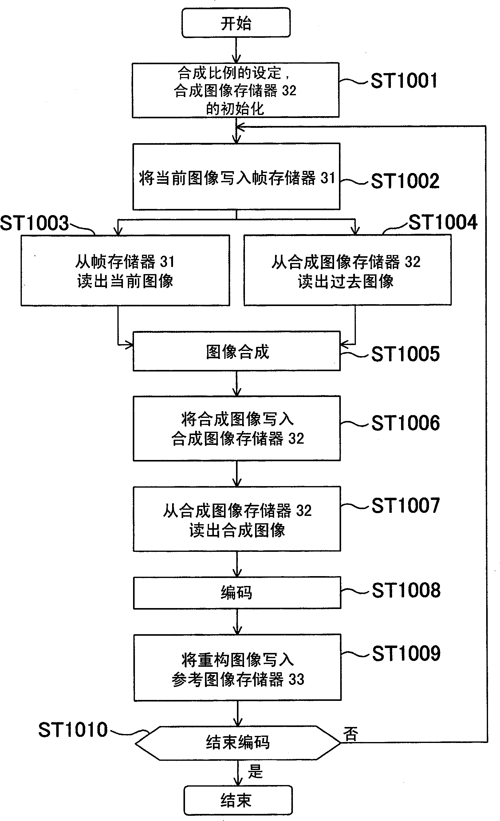
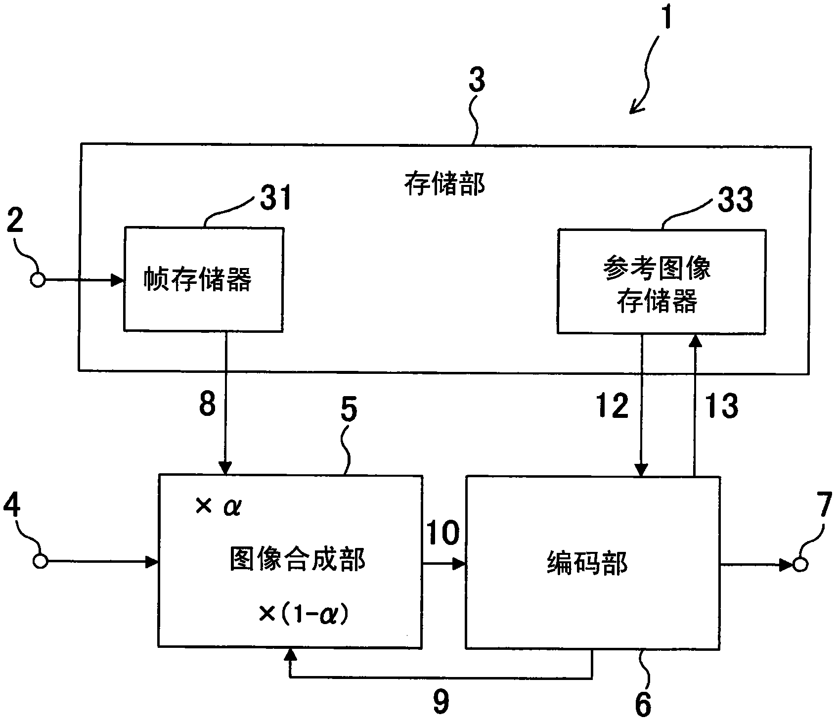
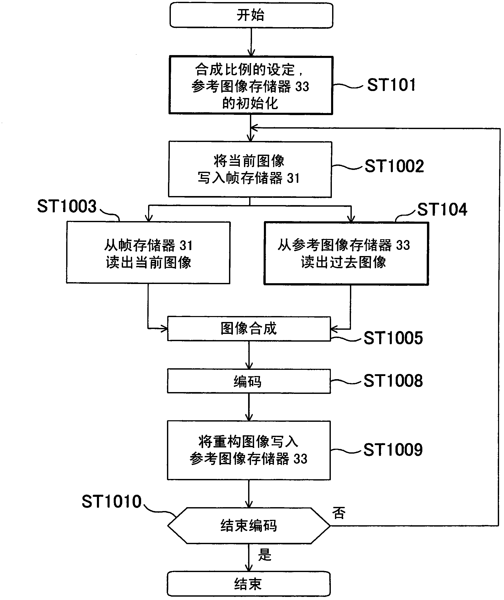
[0074] figure 1 is a diagram showing the image synthesis encoding device 1 according to the first embodiment of the present invention, and Figure 13 The biggest difference of the shown conventional image composite encoding device 101 is that the composite image memory 32 in the storage unit 3 is unnecessary.
[0075] figure 1 The image synthesis encoding device 1 includes an input terminal 2 , a storage unit 3 , a setting terminal 4 , an image synthesis unit 5 , an encoding unit 6 and an output terminal 7 .
[0076] The current image is input to input terminal 2 in sequence.
[0077] The storage unit 3 includes a frame memory 31 and a reference image memory 33 . The frame memory 31 temporarily stores a current image required for image synthesis. The reference image memory 33 temporarily stores reference images required for encoding.
[0078] The setting terminal 4 sets the composition ratio α of the current image 8 sequentially input from the frame memory 31 and the pas...
no. 2 approach
[0103] image 3 It is a diagram showing a schematic configuration of an image composition encoding device 201 according to the second embodiment of the present invention. Figure 4 is a simple representation image 3 A diagram showing the internal structure of the encoding unit 6.
[0104] The difference from the first embodiment is that a reference image memory write control unit 21 ( Figure 4 ) and external setting terminal 20. The reference image memory writing control unit 21 writes the reconstructed image 13 generated in the encoding unit 6 into the reference image memory 33 in units of frames (updates the reference image memory 33) or does not write (does not update the reference image memory 33). control. The external setting terminal 20 sets the update cycle of the reference image memory 33 to the reference image memory writing control unit 21 .
[0105] In the case of the first embodiment, the input current image and the past image are always synthesized and enc...
no. 3 approach
[0116] Figure 7 It is a flowchart of the image composition encoding method according to the third embodiment of the present invention. with the second embodiment ( Figure 5 ) is different in that the motion vector information obtained during sequential encoding in the encoding unit 6 is added to detect the overall motion of the composite image (ST300), so as to adaptively change the control of the update period of the reference image (ST301).
[0117] In the case of the second embodiment, with respect to the frame rate of the input image, the frame rate of the image remaining in the reference image memory 33 as a past image is fixed. Therefore, for example, in the case of capturing a scene with intense motion (the moving distance of the moving object per unit time is relatively large), and in the case of capturing a scene with smooth motion (the moving distance of the moving object per unit time is relatively small) , resulting in the problem of large differences in the re...
PUM
 Abstract
Description
Claims
Application Information
 - R&D
- Intellectual Property
- Life Sciences
- Materials
- Tech Scout
- Unparalleled Data Quality
- Higher Quality Content
- 60% Fewer Hallucinations
Browse by: Latest US Patents, China's latest patents, Technical Efficacy Thesaurus, Application Domain, Technology Topic, Popular Technical Reports.
© 2025 PatSnap. All rights reserved.Legal|Privacy policy|Modern Slavery Act Transparency Statement|Sitemap|About US| Contact US: help@patsnap.com


