Sheet hole punching apparatus and sheet hole punching method
A technology of perforating device and paper, applied in metal processing and other directions, can solve the problems of slowing down the perforation speed, increasing the driving part device, increasing the cost, etc., and achieving the effect of fast perforation
- Summary
- Abstract
- Description
- Claims
- Application Information
AI Technical Summary
Problems solved by technology
Method used
Image
Examples
Embodiment 1
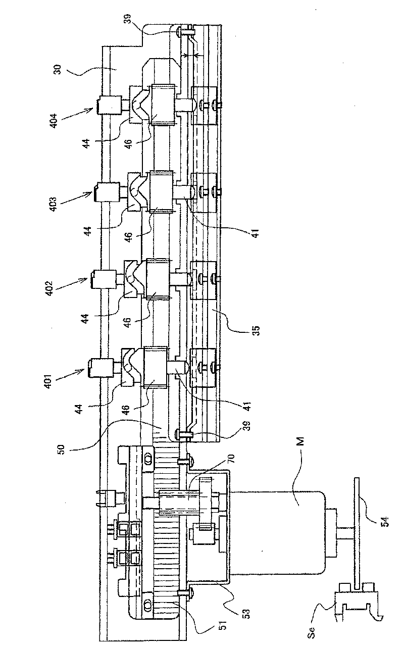
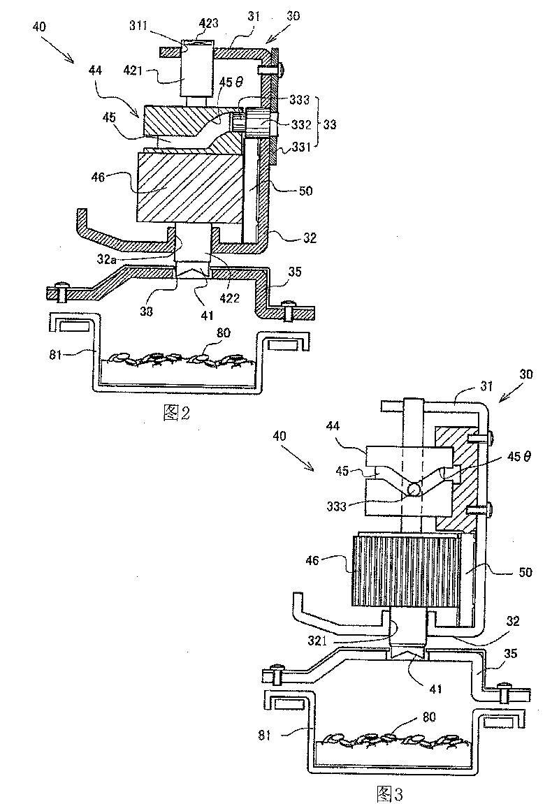
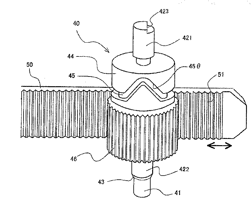
[0039] Such as figure 1 and figure 2 As shown, the punching device of Embodiment 1 consists of an upper base 30 of the corresponding size to the plate to be punched, and a lower base 35 (also called "punching table") spaced between the upper base 30 and the perforated plate. 1. The punching part 40 installed on the upper base 30 and the punching 38 arranged on the lower base 35, the driving motor M, the transmission mechanism and the cam mechanism constitute the above-mentioned punching part 40 which is cylindrical and is provided with an upper shaft 421 And lower shaft 422, and be provided with punching knife 41 at its front end namely lower end, punching part 40 is provided with 2 or 3 or 4 etc. at intervals according to the specification (file hole specification) determined by upper base 30, this There are four in the embodiment: a first punching part 401 , a second punching part 402 , a third punching part 403 and a fourth punching part 404 .
[0040] The punching parts...
Embodiment 2
[0065] see Figure 18 to Figure 22 , Embodiment 2 is described as follows.
[0066] Figure 18 , Figure 19 The illustrated cylindrical cam 66 is fixed to the upper base 30 , and a guide pin 65 coupled with a cam groove 67 of the cylindrical cam 66 is provided on the punching member 62 side. In this embodiment, components having the same structure as those in Embodiment 1 are assigned the same numbers, and descriptions thereof are omitted.
[0067] Upper abutment 30 and lower abutment 35 with figure 1 The parts in the composition are the same, and the two form a whole. The drive shaft 60 connected to the drive motor M is configured on the upper base 30. In addition, the same as the first embodiment, the upper base 30 is provided with an upper guide rail 31 and a lower guide rail 32, and its upper and lower guide holes 311, 321 It is automatically fitted up and down with the piercing member 40 . Four perforating members 40 are arranged, as shown in the figure, which is th...
Embodiment 3
[0073] Such as Figure 23 As shown, the differences between Embodiment 1 and Embodiment 2 in Embodiment 3 will be described below. The structure of the perforating member 62 is basically the same as that of the second embodiment, so the same numbers are used, and descriptions are omitted. Figure 23 The sliding cam 82 shown replaces the eccentric cam 61 in the second embodiment, the sliding cam 82 is connected with the driving motor, and a cam groove 83 with a V-shaped groove 831 is provided on it. The cam groove 83 cooperates with the needle 832 on the top of the punching part 40, and the other structures of the punching part 62 are the same as those in the second embodiment.
[0074] Such as Figure 23 In the left-right direction shown, when the sliding cam 82 is operated back and forth through a given stroke, the pin 832 cooperating with the cam groove 83 moves from the upper apex of the V-shaped groove 831 to the lower apex, and moves to the thrust direction. The punchi...
PUM
 Abstract
Description
Claims
Application Information
 - R&D
- Intellectual Property
- Life Sciences
- Materials
- Tech Scout
- Unparalleled Data Quality
- Higher Quality Content
- 60% Fewer Hallucinations
Browse by: Latest US Patents, China's latest patents, Technical Efficacy Thesaurus, Application Domain, Technology Topic, Popular Technical Reports.
© 2025 PatSnap. All rights reserved.Legal|Privacy policy|Modern Slavery Act Transparency Statement|Sitemap|About US| Contact US: help@patsnap.com


