Minimally invasive spinal disc stabilizer and insertion tool

An intervertebral and vertebral technology, applied in spinal implants, joint implants, joint implants, etc., can solve the problems of large intervertebral disc prosthesis and unsafe posterior access.

Inactive Publication Date: 2008-01-23
布拉德利·J·格伦 +1
View PDF0 Cites 5 Cited by
  • Summary
  • Abstract
  • Description
  • Claims
  • Application Information

AI Technical Summary

Problems solved by technology

Because the anterior access does not address the space constraints that arise in the posterior approach, current disc prostheses are designed to be too large to be safely used in the posterior approach

Method used


Image

  • Minimally invasive spinal disc stabilizer and insertion tool
  • Minimally invasive spinal disc stabilizer and insertion tool
  • Minimally invasive spinal disc stabilizer and insertion tool

Examples


Embodiment Construction

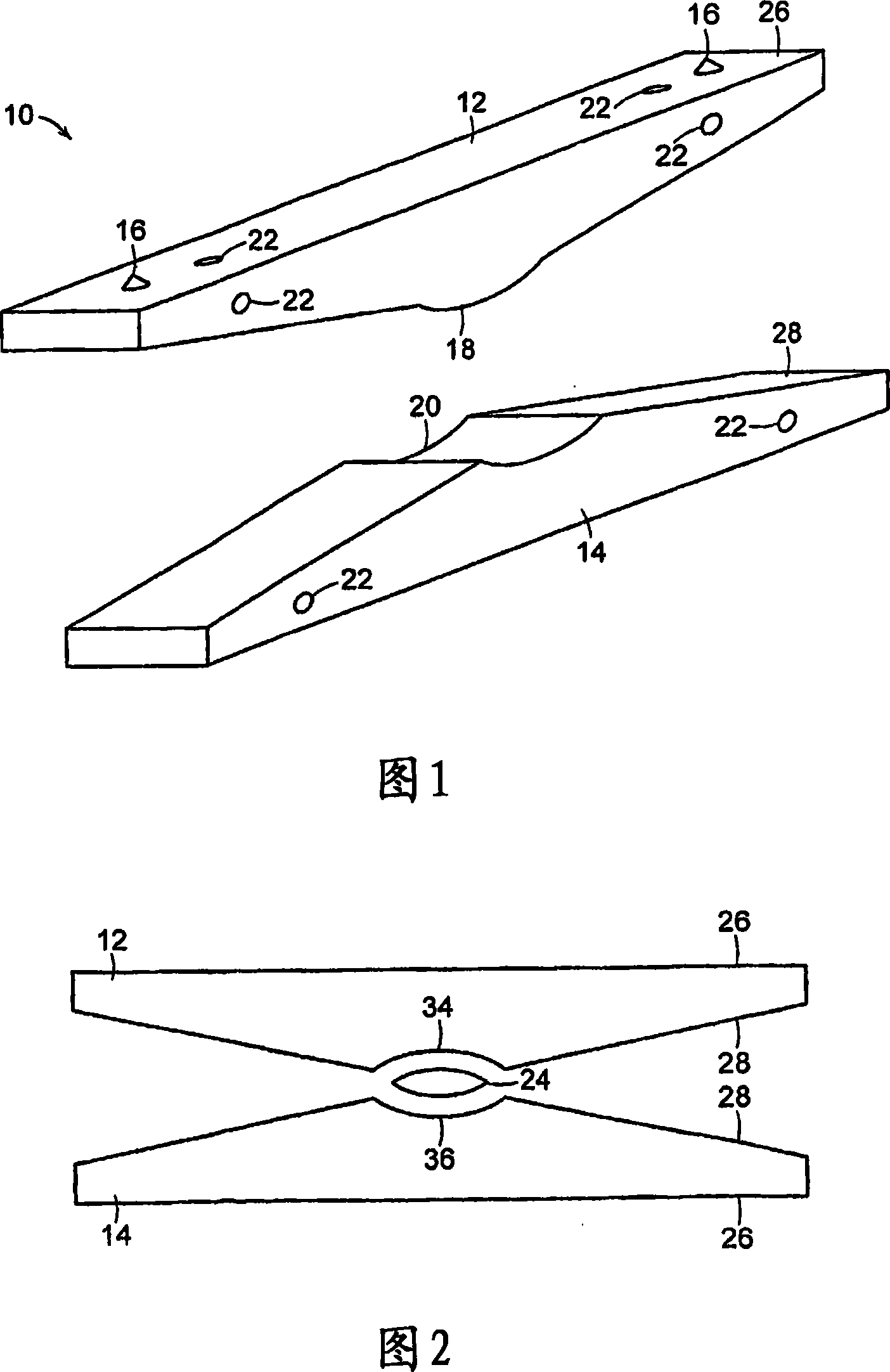
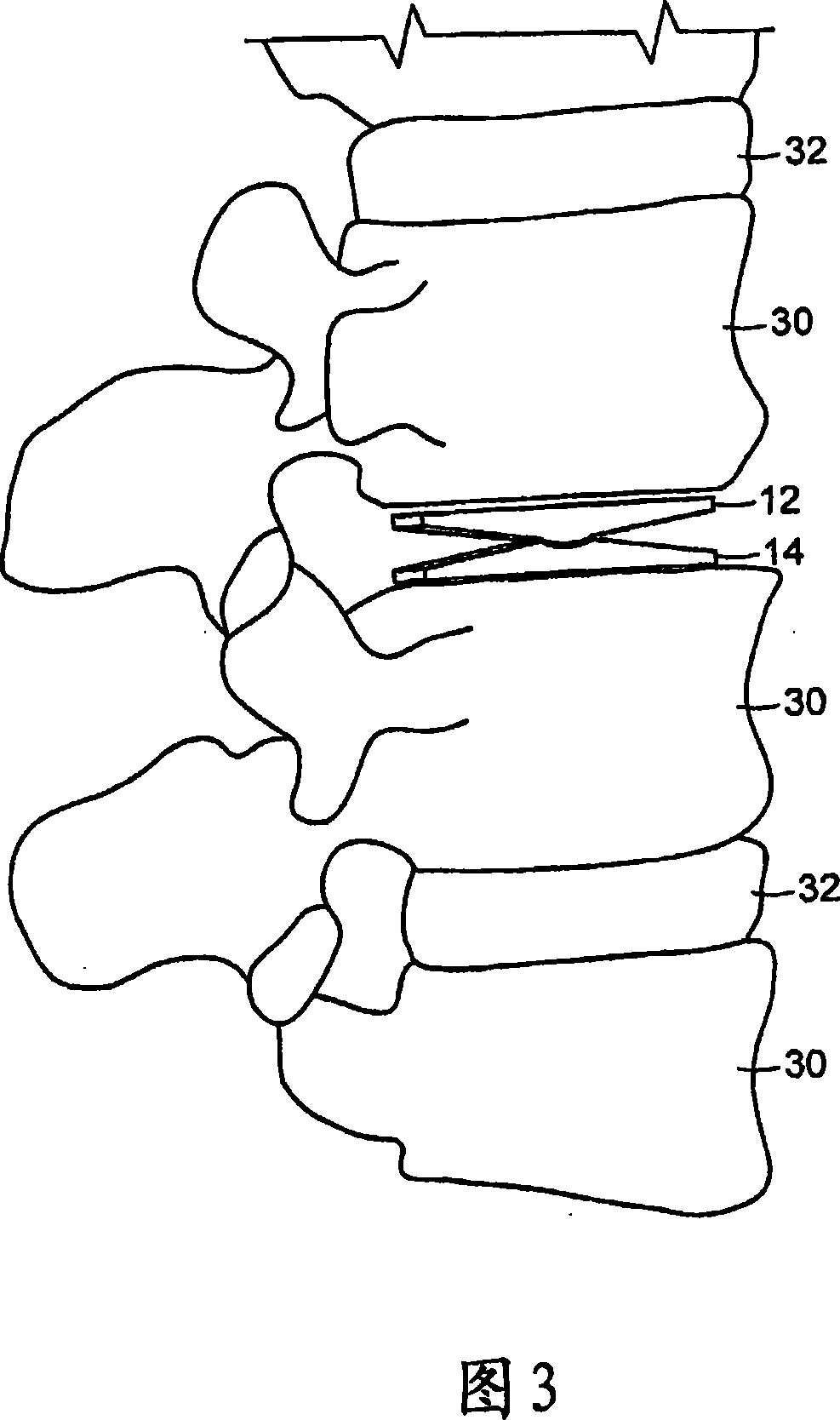
[0095] The present invention provides an implantable device between two vertebrae of the spine to replace or relieve pressure exerted on the intervertebral disc. The instrument comprises at least one upper component and one lower component articulateable about a mechanical connection between the upper and lower components, thereby allowing controllable relative movement between said at least two components. Thus, when placed between and attached or rested on two vertebrae, the implant allows controlled motion between the vertebral components of the axial skeleton similar to that provided by a replaced or supported intervertebral disc.

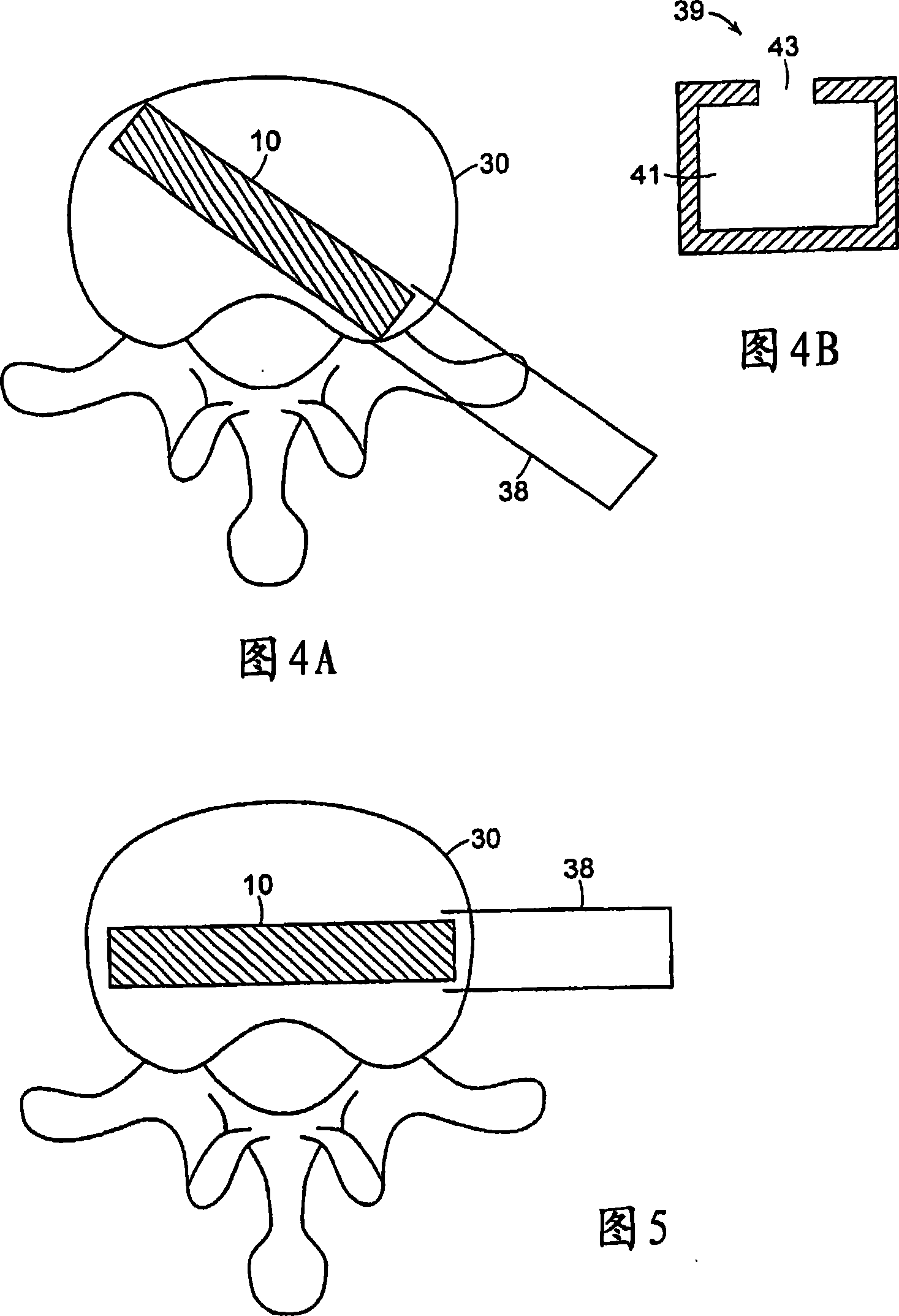
[0096] The present invention also provides a method and device for implanting said device in the intervertebral space. The method uses a minimally invasive approach or access lateral, anterior, or posterior with minimal damage to the soft tissue surrounding the implant. The means for inserting the implant may be used both for inserting the imp...


PUM


Abstract

The invention relates to a spinal implant to be inserted between two vertebra to support and stabilize adjacent vertebra and allow for physiological motion. The invention includes an implantable device to support the vertebrae, and a minimally invasive method for inserting and deploying the device within the intervertebral space.

Description

[0001] This application claims U.S. Provisional Patent Application No. 60 / 629892, dated November 23, 2004 and Application No. 60 / 665874, dated March 29, 2005 and U.S. Utility Model Application No. 11 / 194050, application Priority dated July 29, 2005, the entire contents of which application is hereby incorporated herein by reference. technical field [0002] The present invention relates to the field of spinal implants in general and, more particularly, to an implant configured to be placed within an intervertebral space to support and stabilize adjacent vertebrae and to allow physiological movement. Background technique [0003] The vertebrae are the central axis of bones that support most of the body's weight. In humans, the normal spine has seven cervical vertebrae, twelve thoracic vertebrae and five lumbar vertebrae. The lumbar spine rests on the sacrum, which attaches to the pelvis and is in turn supported by the hip and leg bones. The multiple vertebrae of the spine a...

Claims


Application Information

Patent Timeline
IPC IPC(8): A61F2/44A61F2/46
CPCA61F2/44A61F2002/30001
Inventor 布拉德利·J·格伦加里·A·施奈德曼
Owner 布拉德利·J·格伦
Why Eureka
Try Eureka