Ball valve core and fabrication technology thereof

A technology of manufacturing process and spool, which is applied in the field of ball valve spool and its manufacturing process, can solve the problems of material waste and high production cost, and achieve the effect of reducing production cost and saving materials

Inactive Publication Date: 2008-01-30
金济定
View PDF0 Cites 15 Cited by
  • Summary
  • Abstract
  • Description
  • Claims
  • Application Information

AI Technical Summary

Problems solved by technology

[0003] The present invention mainly aims at the technical problems of excessive material waste and high production cost in the prior art, thereby providing a ball valve core with material saving and low production cost and its manufacturing process

Method used


Image

  • Ball valve core and fabrication technology thereof
  • Ball valve core and fabrication technology thereof
  • Ball valve core and fabrication technology thereof

Examples


Embodiment 1

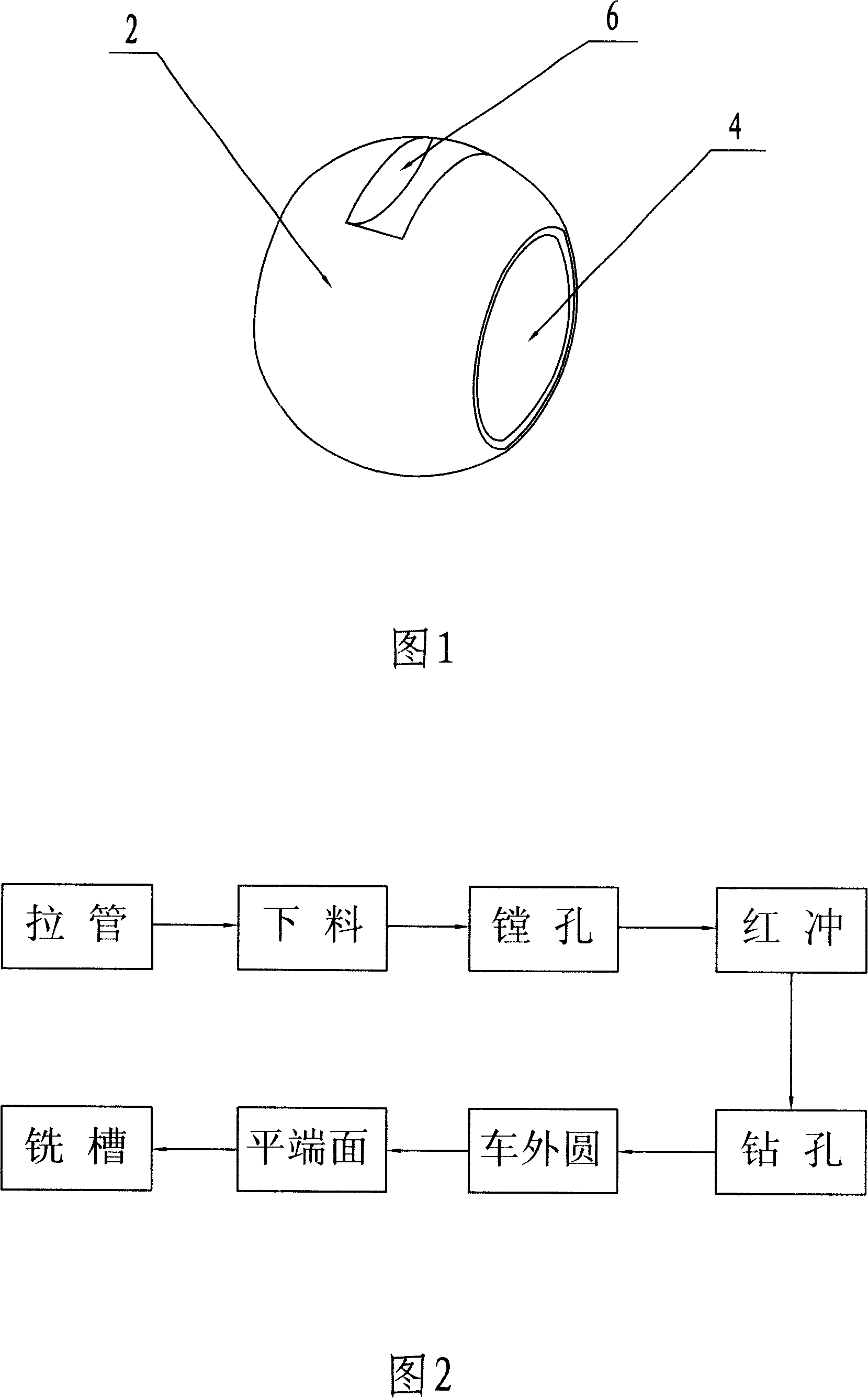
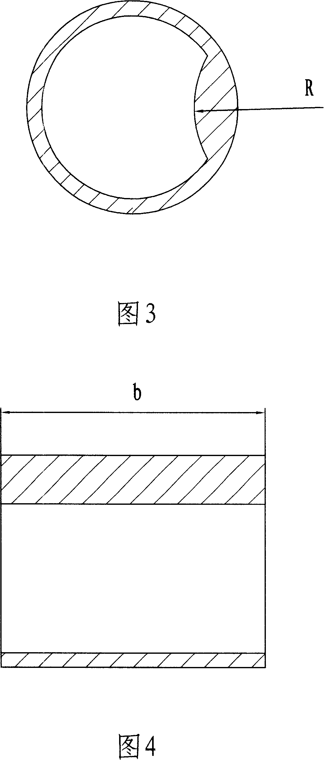
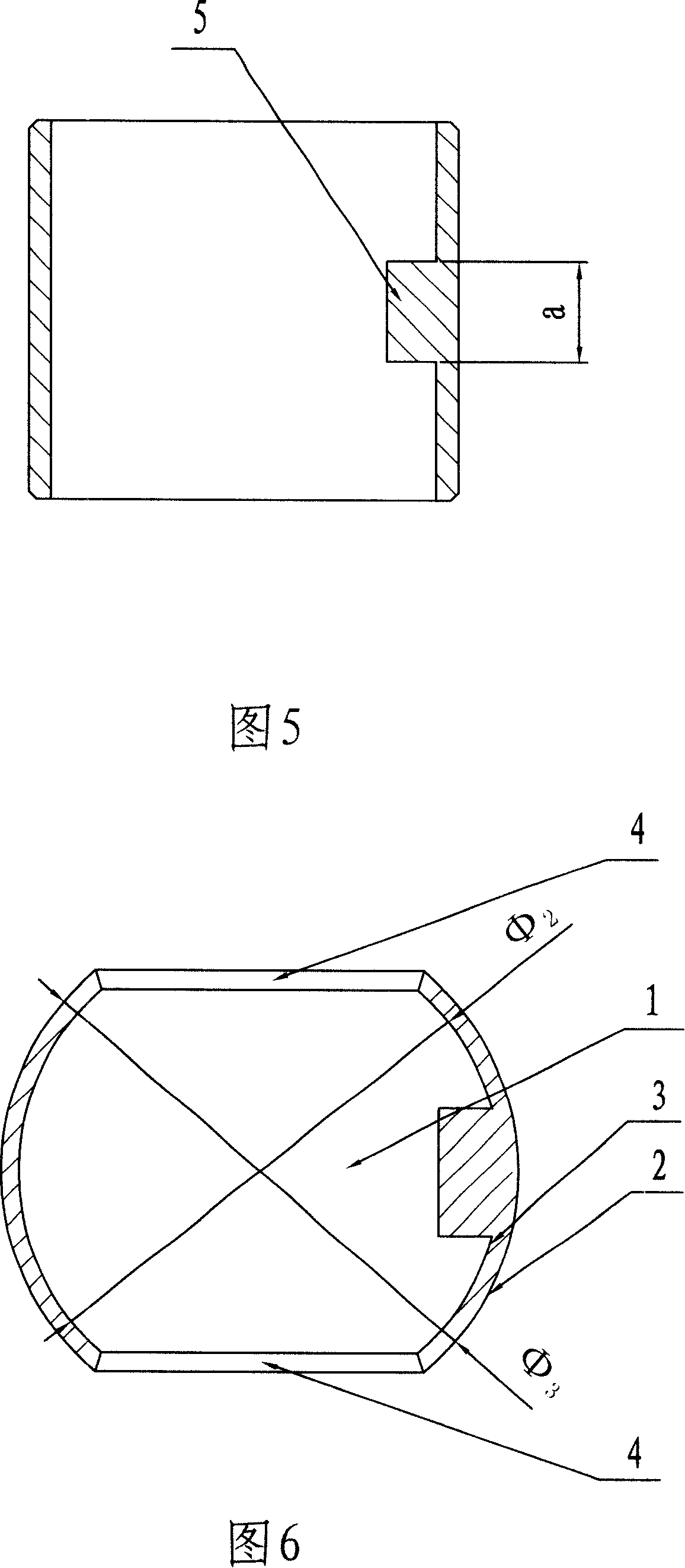
[0033] Embodiment 1: As shown in Figure 1, the spool of the ball valve is in a spherical structure as a whole, and a groove 6 is arranged on the outer spherical surface 2, and the groove 6 is set at the center of the outer spherical surface 2, and at the same time, the two sides of the spool of the ball valve Two side holes 4 are provided on the side. There is an inner hole 1 at the center, and the inner hole 1 runs through the whole sphere through two side holes 4. At the same time, the inner hole 1 is spherical, forming an outer spherical surface 2 and an inner spherical surface 3, and the outer spherical surface 2 and the inner spherical surface 3 constitute a A ball wall 7 with a thickness of 1.8 mm. At the central position of the inner spherical surface 3, a boss 5 is laterally arranged. The width of the boss 5 is 11 mm. The boss 5 is an arc surface, and the radius R of the arc surface is 26.8 mm. There is a groove 6 with a length of 24.5mm and a width of 8mm at the cent...


PUM

PropertyMeasurementUnit
thicknessaaaaaaaaaa
thicknessaaaaaaaaaa
radiusaaaaaaaaaa

Abstract

The invention relates to a valve core of a spherical valve and a manufacturing technique thereof. The valve core of the spherical valve is manufactured through such processes as tube drawing, blanking, borizing, red punching, drilling, external cutting, end surface leveling, and slot milling; the valve core comprises a sphere body, an inner hole arranged in the center position of the sphere body and passing through the whole sphere body which is a ball shape and forms two side holes on the surface of the sphere body, and a slot arranged on the surface of the spherical surface. The center position of the inner sphere surface is provided with a circular surfaced boss, the slot is positioned at the center position of outer sphere surface corresponding to the boss. Since the sphere wall thickness is uniformity after being manufactured, the material is saved and the production cost is cut down.

Description

technical field [0001] The invention belongs to the technical field of ball valves, and in particular relates to a ball valve core and a manufacturing process thereof. Background technique [0002] Valves are widely used in modern society. Such as in water tap, at present, known water tap is provided with valve rod in valve body, and the lower end of valve rod is connected with rubber pad. When working, rotate the valve stem to make the rubber pad move up; when closing, reversely rotate the valve stem to make the rubber pad move down. But because the sealing surface between the rubber pad and the valve body can keep a very small gap, the water meter does not rotate when dripping occurs, thereby leaving an opportunity for water thieves. Therefore, the ball valve is more in line with the requirements of use. As an important part of the ball valve, the spool has a symmetrical spherical structure as a whole, with a cylindrical inner hole penetrating the whole in the middle, a...

Claims


Application Information

Patent Timeline
Patent Type & Authority Applications(China)
IPC IPC(8): F16K5/06B23P13/02
Inventor 金济定
Owner 金济定
Why Eureka
Try Eureka