Lens cap device

A lens cover and lens technology, applied in projection devices, instruments, optics, etc., can solve problems such as affecting the action of the lens cover, inaccurate linkage transmission, and oil leakage.

Inactive Publication Date: 2008-01-30
AIXIN TECH
View PDF0 Cites 10 Cited by
  • Summary
  • Abstract
  • Description
  • Claims
  • Application Information

AI Technical Summary

Problems solved by technology

[0004] Another existing design is an electric lens cover, such as Taiwan Patent No. 512255, which uses the power on and off to control the stepping motor to drive the gear and rack structure to drive the lens cover to open and close. However, this technology is prone to inaccurate interlocking transmission due to dust problems, and even related mechanisms are stuck, making it impossible to open and close the lens cover, and the temperature inside the projector will affect the stepping motor, resulting in dry lubricating oil or oil leakage. Affect the action of the lens cover, and it will greatly increase the cost, which is not economical
Moreover, the opening and closing of the lens cover can only be controlled electrically. If the user does not cover the lens cover and then shuts down the projector first, the lens cover needs to be powered on again to cover the lens cover, which affects the convenience of the user's operation.

Method used


Image

  • Lens cap device
  • Lens cap device
  • Lens cap device

Examples


Embodiment Construction

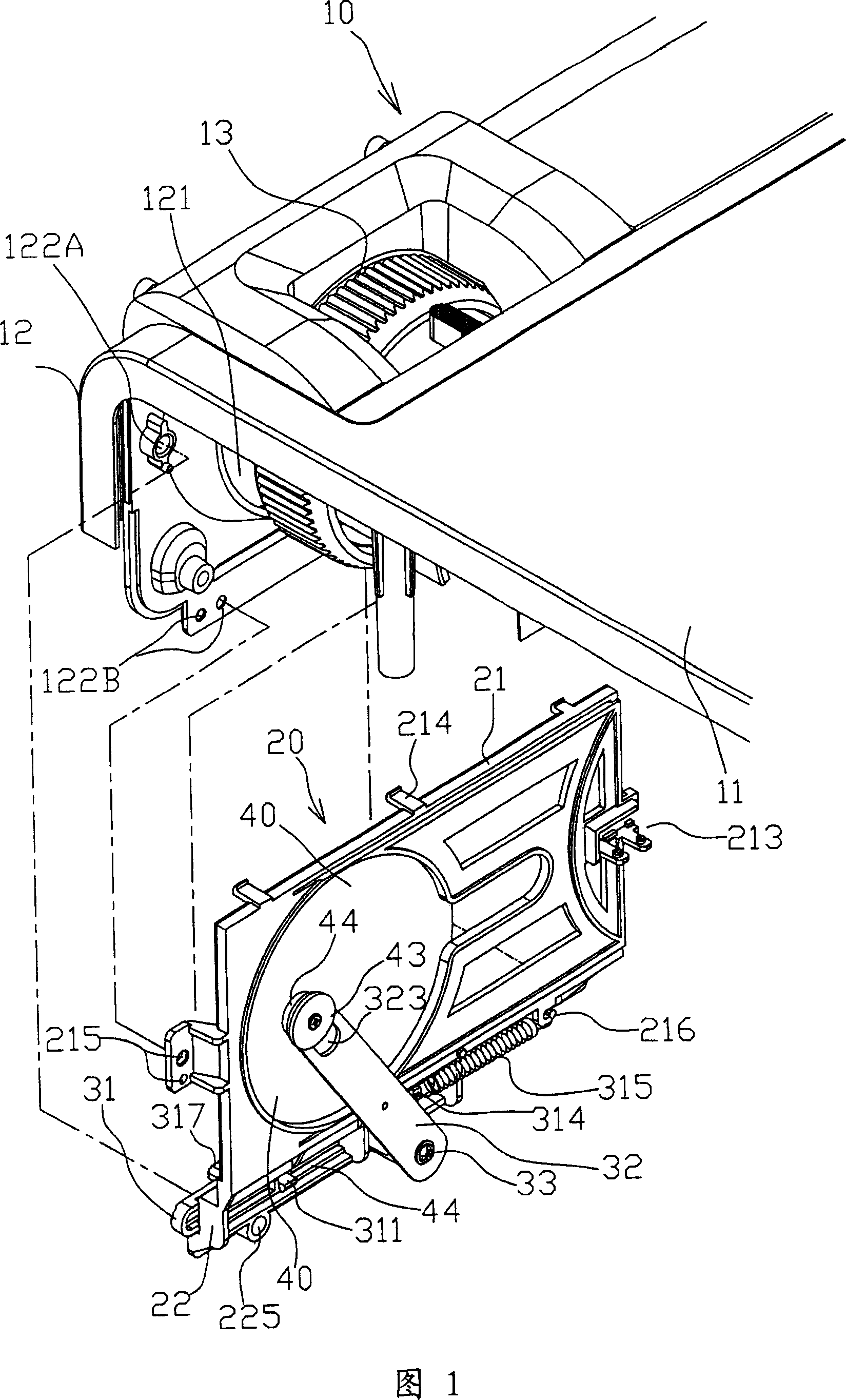
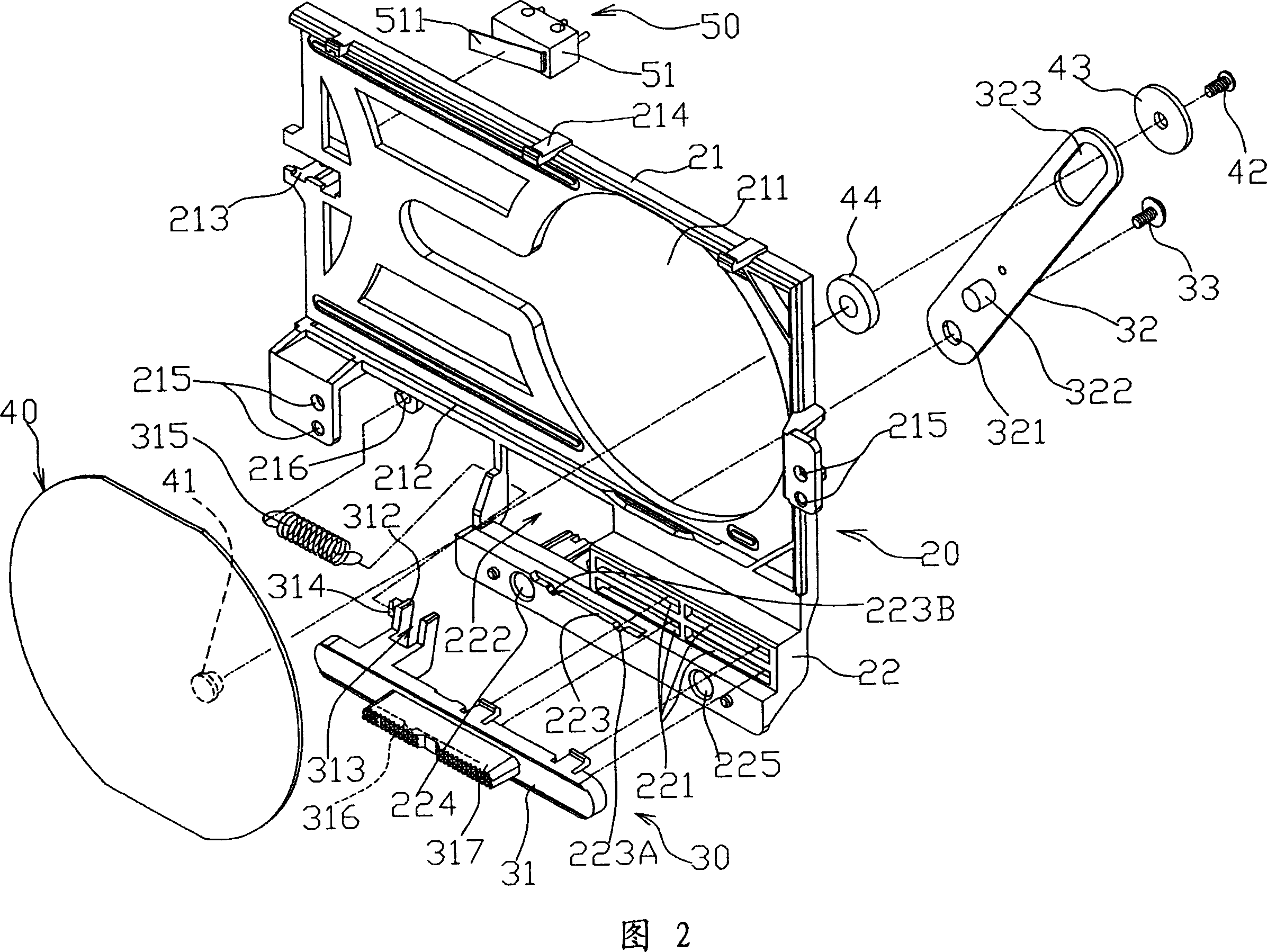
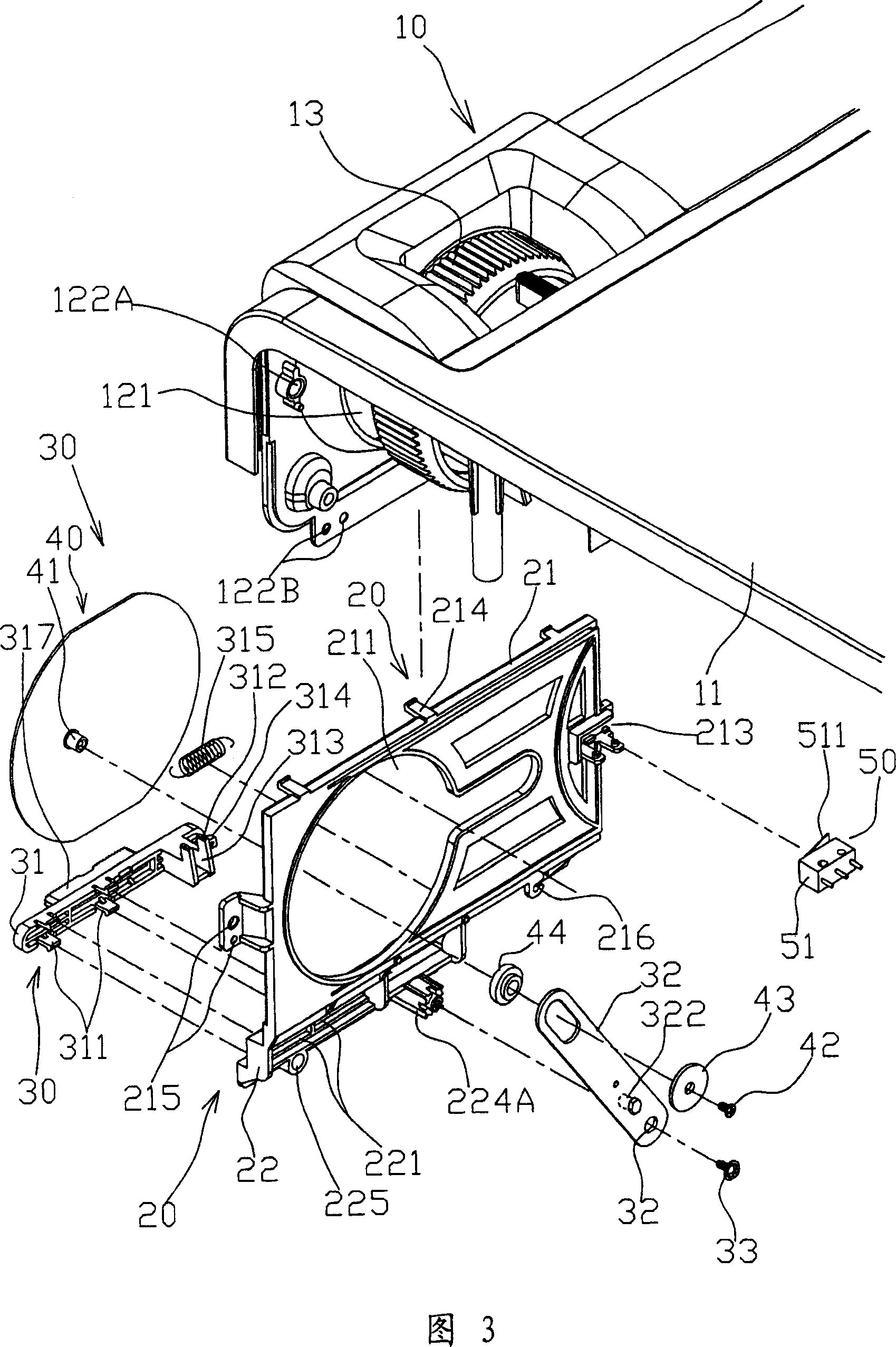
[0043] Referring to Fig. 1, Fig. 2 and Fig. 3, the lens cover device of the present invention includes a body device 10, a cover device 20, an interlocking mechanism 30, a lens cover 40 and a sensing device 50; wherein, the body device 10 includes a Body 11, the body 11 has a body front cover 12 formed with a lens through hole 121, and the body front cover 12 is provided with a plurality of fixing holes 122A, 122B, etc., and the body 11 is provided with a lens through hole 121. lens 13 , and a space is formed between the lens 13 inside the body 11 and the front cover 12 of the body.

[0044] The protective cover device 20 is arranged on the body 11 of the body device 10, and is located in the space between the lens 13 and the front cover 12 of the body. It includes a protective cover 21 and a protective cover seat 22. The protective cover 21 is provided with a The lens through hole 211 of the lens through hole 121, the outer inner surface of the protective cover 21 is provided...


PUM


Abstract

The invention relates to a lens cover device, comprising a shielding cover device, wherein, the shielding cover device comprises a shielding cover which is provided with a lens through-hole; a linkage device which consists of a pushing part and a linkage part, and the pushing part is glidingly embedded on the shielding cover device, and one end of the linkage part is pivotally connected with the shielding cover device to form a fulcrum; the linkage part is drivingly connected with the pushing part; and also comprising a lens cover which is glidingly arranged on the shielding cover device, and the lens cover is pivotally connected with the other end of the linkage part which is opposite to the fulcrum to form a linkage state between the lens cover and the linkage part. And the lens cover is driven by the linkage part to shield or open the lens through-hole.

Description

technical field [0001] The present invention relates to a lens cover device, in particular to a lens cover device which makes the lens cover thinner and uses a magnifying linkage mechanism to control the rapid sliding of the lens cover so as to facilitate the lens protection operation. Background technique [0002] Projector is a video equipment commonly used by modern people. It is widely used in presentations, conferences, education and training, or film and television entertainment. It mainly uses a lens to project data to the outside world (such as a screen, etc.). It affects the imaging quality of its image data projection. Therefore, a general projector is provided with a lens cover to protect the lens from being scratched or stained. Since the exposed lens cover is arranged on the outside of the projector, and the lens cover needs to be removed before using the projector, the lens cover is easy to drop and lose, which often causes troubles for users. Furthermore, if ...

Claims


Application Information

Patent Timeline
IPC IPC(8): G03B21/14
Inventor 张汎杰刘义铭
Owner AIXIN TECH
Why Eureka
Try Eureka