Method and device for enhancing transmitting-receiving isolation of mobile terminal

A technology of transceiver isolation and mobile terminal, applied in waveguide-type devices, circuits, transmission systems, etc., can solve problems such as unsatisfactory effect, duplexer transceiver isolation, single-board device layout and wiring, etc., to reduce isolation. degree requirements, the improvement of transceiver isolation, and the effect of reducing linearity requirements

Inactive Publication Date: 2008-01-30
ZTE CORP
View PDF0 Cites 27 Cited by
  • Summary
  • Abstract
  • Description
  • Claims
  • Application Information

AI Technical Summary

Problems solved by technology

[0027] 3) Since the maximum transmission power of the mobile terminal is fixed, PTX is mainly affected by the transceiver isolation. For traditional mobile terminals, it is greatly affected by the transceiver isolation of the duplexer and the layout and routing of single-board devices.
[0028] 4) The IIP3 index of the LNA is a measure of the linearity index of the amplifier. This index generally needs to be compromised with the LNA noise figure, LNA gain, operating current and other indicators. For example, the LNA can be improved by reducing the gain or increasing the operating current. IIP3 indicators, etc., but this often sacrifices indicators such as receiving sensitivity and talk time
However, the existing technology mainly relies on transmission lines and duplexers to determine the transceiver isolation, and the effect is not ideal

Method used


Image

  • Method and device for enhancing transmitting-receiving isolation of mobile terminal
  • Method and device for enhancing transmitting-receiving isolation of mobile terminal
  • Method and device for enhancing transmitting-receiving isolation of mobile terminal

Examples


Embodiment Construction
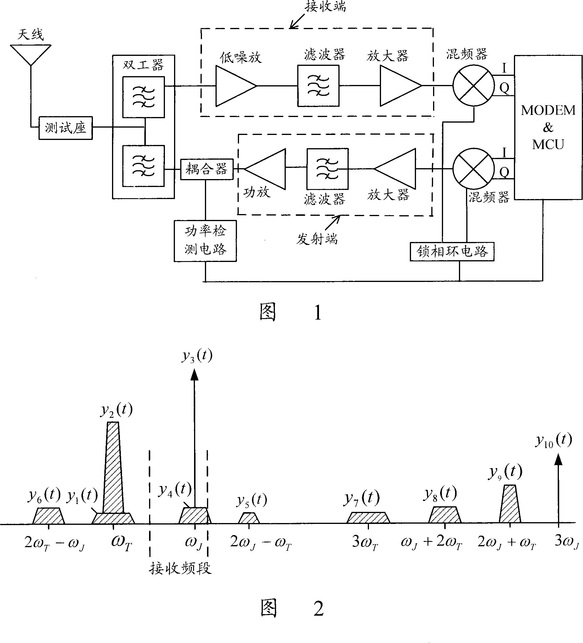
[0049] The basic idea of ​​the present invention is: improve the transceiver isolation circuit of the existing mobile terminal, add a transceiver isolation device, couple the leakage signal before entering the low noise amplifier, reduce the amplitude of the transmission frequency signal, and reduce the LNA intermodulation distortion signal interference with the received signal.

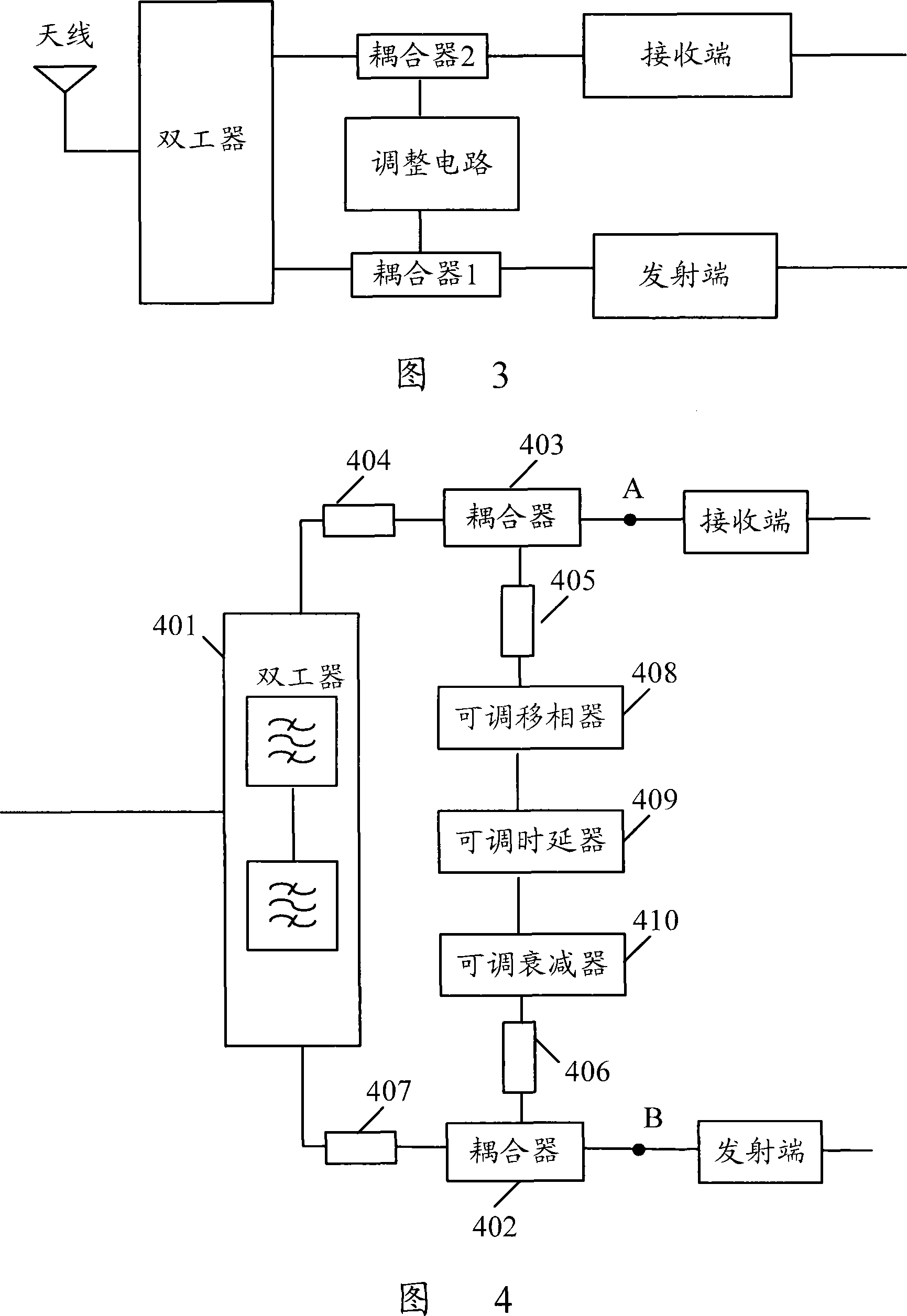
[0050] The device for improving the transceiver isolation of a mobile terminal in the present invention includes two couplers and an adjustment circuit. As shown in Figure 3, the coupler 1 is connected to the duplexer and the receiving end, and connected to the adjustment circuit, which is used to couple the leakage signal from the duplexer with the adjustment signal from the adjustment circuit, and couple the coupled signal Transmit to the receiving end; the adjustment circuit is used to adjust part of the transmitted signal, and transmit the adjusted signal to the coupler 1; the coupler 2 is connec...


PUM


Abstract

The invention discloses a device for improving the transmitting and receiving isolation of a mobile terminal, which is positioned between a diplexer and a signal receiving terminal. The device comprises a first coupler which is connected with the diplexer and the signal receiving terminal and is also connected with a modulation circuit and used for coupling a leak signal transmitted from the diplexer with a modulated signal transmitted from the modulation circuit; then the signal after coupling is transmitted to the receiving terminal; and the device also comprises the modulation circuit which is used for modulating a part of an emitting signal and sending the signal after modulation to the first coupler and a second coupler which is connected with the diplexer and an emitting terminal and is also connected with the modulation circuit and is used for coupling a part of the emitting signal to output to the modulation circuit. The invention also discloses a corresponding method to determine the modulation circuit structure and the modulation values of the amplitude, the delay and the phase regulating values of the part of the emitting signal according to the leak signal; the modulation signal is coupled with the leak signal, and the signal after coupling is input into the receiving terminal. The invention can improve the quality of receiving signals, reduce the requirements of the diplexer and so on to isolation and extend standby time.

Description

technical field [0001] The invention relates to a signal receiving and sending isolation technology of a mobile communication terminal, in particular to a method and a device for improving the sending and receiving isolation of a mobile terminal. Background technique [0002] For a mobile terminal whose receiving and transmitting links work simultaneously, the transceiver isolation is a very important performance index, which has a great impact on the performance of the mobile terminal. The so-called transceiver isolation refers to the attenuation of the signal strength when the transmitted signal enters the receiving end. When the receiving and transmitting links of the mobile terminal work at the same time, if the isolation between the receiving and transmitting links is low, part of the energy of the transmitting signal will leak into the low noise amplifier (LNA, Low Noise Amplifier) ​​of the receiving link. At the input end, the leaked transmission signal and the inter...

Claims


Application Information

Patent Timeline
Patent Type & Authority Applications(China)
IPC IPC(8): H04B1/50H04B1/48H01P1/36
Inventor 李远勇
Owner ZTE CORP
Why Eureka
Try Eureka