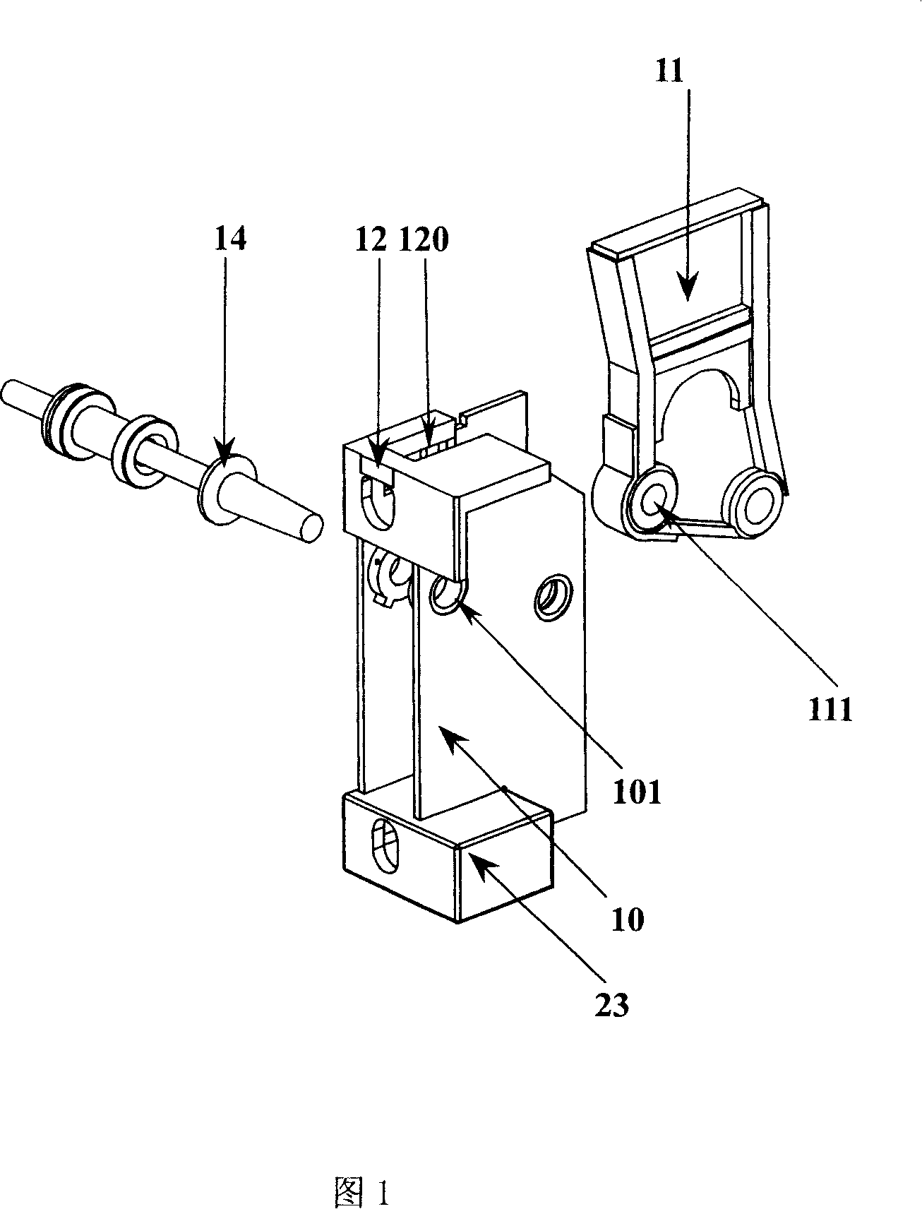
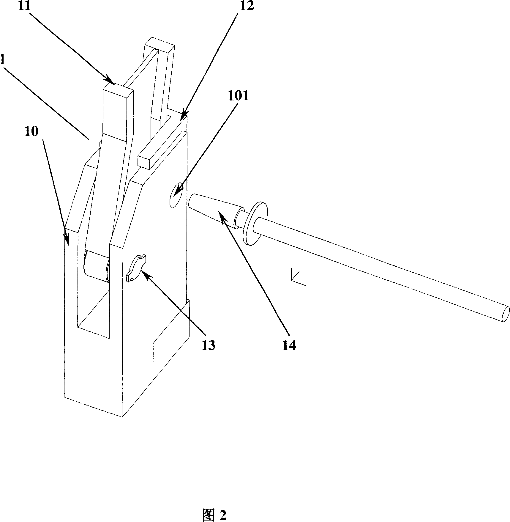
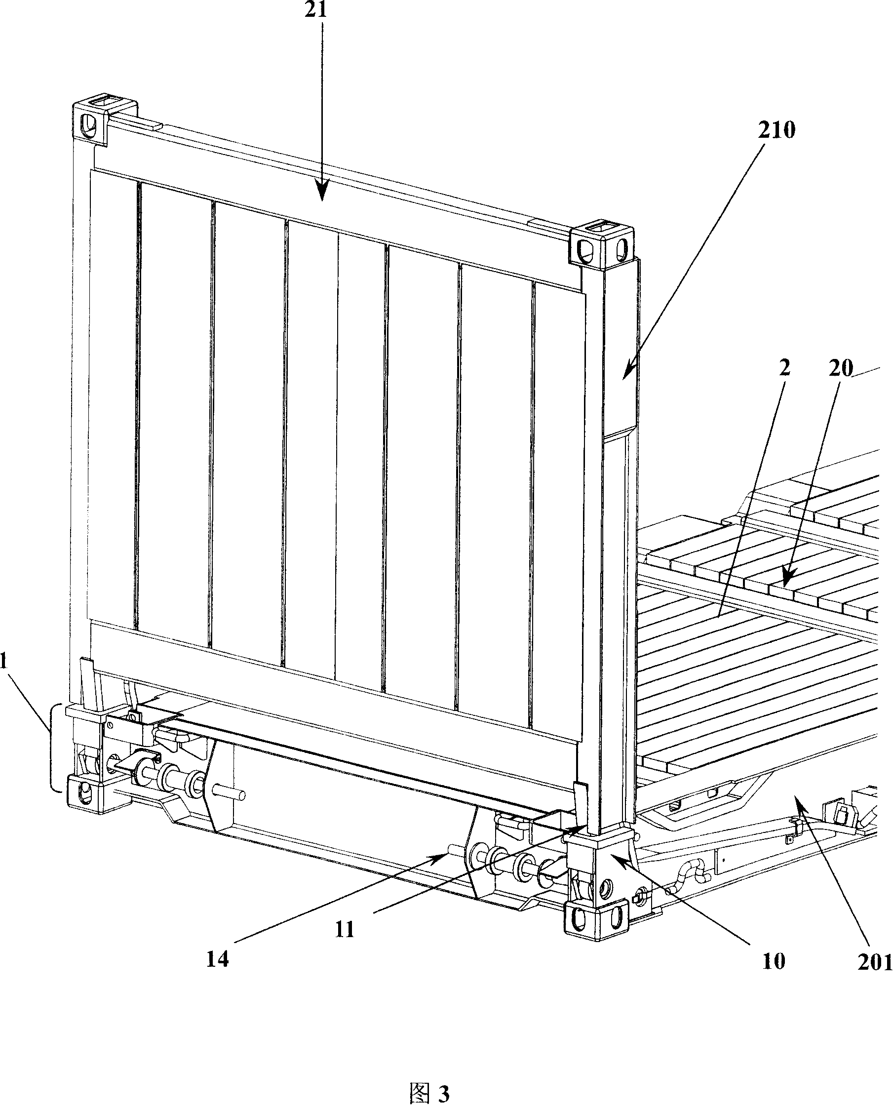
Hinge for folding case
A folding box and hinge technology, applied in the field of folding box hinges and components for folding boxes, can solve the problems of strengthening the inner hinge, the lateral rigidity of the hinge 1 is difficult to meet the requirements, etc., and achieves the effect of increasing the rigidity and increasing the lateral width.
- Summary
- Abstract
- Description
- Claims
- Application Information
AI Technical Summary
Problems solved by technology
Method used
Image
Examples
Embodiment 1
[0032] The hinge for a folding box of the present invention as shown in FIG. 6 includes an inner hinge 31 composed of two parallel inner hinge plates 310 with a certain distance, and two outer hinge plates 301 parallel to each other and a certain distance from each other. The outer hinge 30. Among them, a reinforcing plate is also provided between the two outer hinge plates, which mainly plays a role of strengthening. In this embodiment, since the shape of the reinforcing plate is the same as that of the outer hinge plate 301, the reinforcing plate is usually directly called the outer hinge. The top of the outer hinge 30 is fixedly connected with a hinged top plate 32, the top plate is preferably inverted "L" shape, the hinged top plate 32 is arranged side by side along the width of the box with two receiving grooves for receiving two inner hinge plates 310 321. When assembling the hinge, place the two inner hinge plates 310 between the three outer hinge plates 301 (referring to t...
Embodiment 2
[0038]As shown in Figure 8, another embodiment of the hinge of the present invention. The structure of the hinge is basically the same as that of the first embodiment, only the structure of the inner hinge plate and the locking device are changed. The specific solution is: three square slots 3101 are correspondingly opened at the rear of the three inner hinge plates 310, and three square holes 303 are correspondingly opened at the rear of the three outer hinge plates 30. When the inner hinge plate 310 is standing relative to the outer hinge At the beginning, the square pin 35 can be inserted into the square groove 3101 and the square hole 303 to lock the inner and outer hinges.
Embodiment 3
[0040] As shown in Figures 9, 10, the third embodiment of the hinge of the present invention. The structure of the hinge is basically the same as that of the first embodiment. Only some changes are made to the structure of the inner hinge 31. The specific solution is to connect the bottoms of the two inner hinge plates into one body, so that the inner hinge becomes a whole structure. The bottom of the inner hinge plate is connected into an integral inner hinge structure, and the matching outer hinge is composed of two parallel outer hinge plates with a certain distance from each other, and the hinge top plate on the top of the outer hinge is juxtaposed along the width of the box. Two receiving grooves are provided for receiving two inner hinge plates with the bottom connected as a whole and the top separated. Of course, according to the connection mode of the two inner hinges, a corresponding reinforcing plate can be provided between the two parallel outer hinge plates to achieve ...
PUM
 Abstract
Description
Claims
Application Information
 - R&D
- Intellectual Property
- Life Sciences
- Materials
- Tech Scout
- Unparalleled Data Quality
- Higher Quality Content
- 60% Fewer Hallucinations
Browse by: Latest US Patents, China's latest patents, Technical Efficacy Thesaurus, Application Domain, Technology Topic, Popular Technical Reports.
© 2025 PatSnap. All rights reserved.Legal|Privacy policy|Modern Slavery Act Transparency Statement|Sitemap|About US| Contact US: help@patsnap.com


