Self-supporting gate or gate sliding on a rail

A self-supporting, fence gate technology, applied in the field of fence gates, can solve problems such as not being raised

Inactive Publication Date: 2008-02-06
DIRICKX GRP SA
View PDF0 Cites 16 Cited by
  • Summary
  • Abstract
  • Description
  • Claims
  • Application Information

AI Technical Summary

Problems solved by technology

[0005] Despite many advances and improvements in the field of self-supporting or sliding on rails fence gates, no effective solution has been proposed so far to overcome the above disadvantages

Method used


Image

  • Self-supporting gate or gate sliding on a rail
  • Self-supporting gate or gate sliding on a rail
  • Self-supporting gate or gate sliding on a rail

Examples


Embodiment Construction

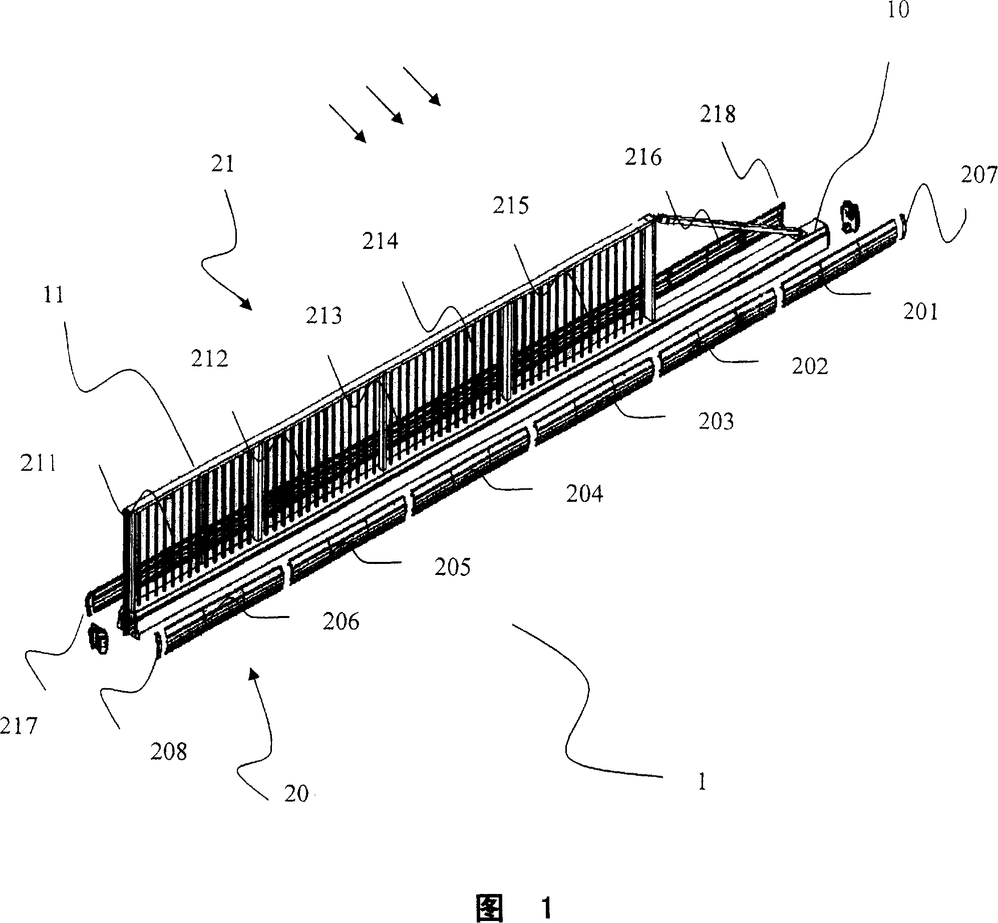
[0030] The self-supporting fence gate 1 of the present invention shown in FIG.

[0031] As indicated by the arrow, the self-supporting fence gate 1 is exposed to sunlight on one side thereof.

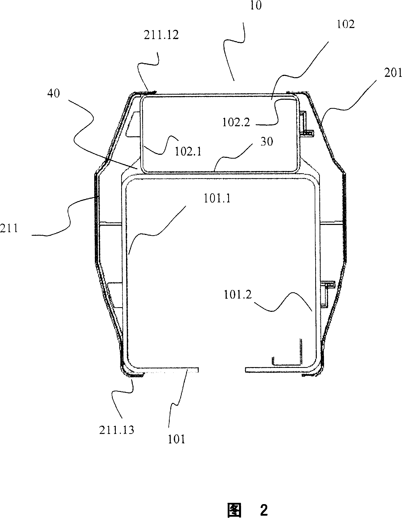
[0032] As shown in Fig. 2, the bottom beam 10 is composed of two units, 101 and 102, respectively. The lower unit 101 has a hollow rectangular shape with its opening facing downwards to allow a guide mechanism (not shown in the figure) to pass through, and the guide mechanism allows the self-supporting fence gate 1 to slide. The upper unit 102 is also in the shape of a hollow rectangle and placed on the top of the unit 101 . The structure in which the bottom beam 10 is divided into two units 101 and 102 improves the conduction of heat generated due to exposure to sunlight from the exposed side to the non-exposed side of the bottom beam 10 . In fact, the interface between unit 101 and unit 102 creates a thickness margin, thus creating a heat transfer zone 30, allowing accelerated heat ...


PUM


Abstract

The present invention relates to a self-supporting gate or a gate sliding on a rail (1) designed to obstruct an entrance passage of variable length that is insensitive to the effects of solar radiation and thus to the temperature differences between the lateral faces of the gate. For this purpose, a self-supporting gate or a gate sliding on a rail (1) according to the invention is of the type that comprises a panel (11) whose base consists of a lower beam (10) and is noteworthy in that it comprises insulating walls (20, 21) arranged laterally on each side of said lower beam (10) along the full length of said lower beam (10) to absorb differential thermal expansion with said lower beam (10). The lower beam (10), thus protected from solar radiation by said insulating walls (20, 21) no longer has any curvature that would prevent correct operation of the gate (1).

Description

technical field [0001] The present invention relates to a self-supporting or rail-sliding fence gate of variable length for blocking passage through, the fence gate comprising a guardrail the bottom of which is formed by a bottom beam. Background technique [0002] Fence gates that are self-supporting or slide on tracks are often used to block entrances through industrial areas. A self-supporting fence gate raised above the ground and comprising a bottom beam supported in a cantilevered manner (en porte à faux) on at least one fixed point. [0003] Rail-sliding fence gates also include a sill fitted with casters for movement along rails fixed to the ground. [0004] During the day, the fence gate can be exposed sideways to sunlight. This then results in that the sides of the fence gate are not exposed to sunlight at the same time. For larger fence gates, the heat generated by sunlight may take a long time to transfer from one side to the other, say ten minutes. Temperatu...

Claims


Application Information

Patent Timeline
Patent Type & Authority Applications(China)
IPC IPC(8): E06B11/02
CPCE06B3/301E06B11/045E06B11/02
Inventor J-M·戈蒂埃L·冯
Owner DIRICKX GRP SA
Why Eureka
Try Eureka