Touch Sensing Catheter

a technology of force sensing and catheter, which is applied in the field of force sensing devices, can solve the problems of time-consuming, complicated mapping procedure, and rely on manual feedback

Active Publication Date: 2008-11-27
ST JUDE MEDICAL INT HLDG SARL
View PDF99 Cites 208 Cited by
  • Summary
  • Abstract
  • Description
  • Claims
  • Application Information

AI Technical Summary

Benefits of technology

[0021]Various embodiments of the invention largely counter the effects of bulk temperature change on the strain elements of a force sensor suitable for use in a low profile assembly, such as a catheter. In various embodiments, a catheter comprising a flexible elongated body includes a strain sensor assembly affixed thereto. The strain sensor assembly includes a deformable structure having a plurality of optical fibers associated therewith. The deformable structure is strained by the imposition of a contact force transferred to the str

Problems solved by technology

Often, the mapping procedure is complicated by difficulties in locating the zone(s) to be treated due to periodic movement of the heart throughout the cardiac cycle.
One drawback of such previously known mapping systems is that they rely on manual feedback of the catheter and/or impedance measurements to determine when the catheter is properly positioned in the vessel or organ.
Those systems do not measure contact forces with the vessel or organ wall or detect contact forces applied by the catheter against the organ or vessel wall that may modify the true wall location.
Instead, previously known mapping methods are time-consuming, dependent upon the skill of the clinician, and cannot compensate for artifacts created by excessive contact forces.
Such arrangements, however, may be inherently imprecise due to the motion of the organ or vessel.
Moreover, the previously-known systems do not provide the ability to sense the load applied to the distal extremity of the catheter by movement of the tissue wall.
For example, in the case of a cardiac ablation system, at one extreme the creation of a gap between the end effector of the treatment system and the tissue wall may render the treatment ineffective, and inadequately ablate the tissue zone.
At the other extreme, if the end effector of the catheter contacts the tissue wall with excessive force, it may inadvertently puncture the tissue, resulting in cardiac tamponade.
One drawback of such devices, however, is that they are relatively complex and must be sealed to prevent blood or other liquids from disturbing the measurements.
In addition, such load sensi

Method used


Image

  • Touch Sensing Catheter
  • Touch Sensing Catheter
  • Touch Sensing Catheter

Examples


Embodiment Construction

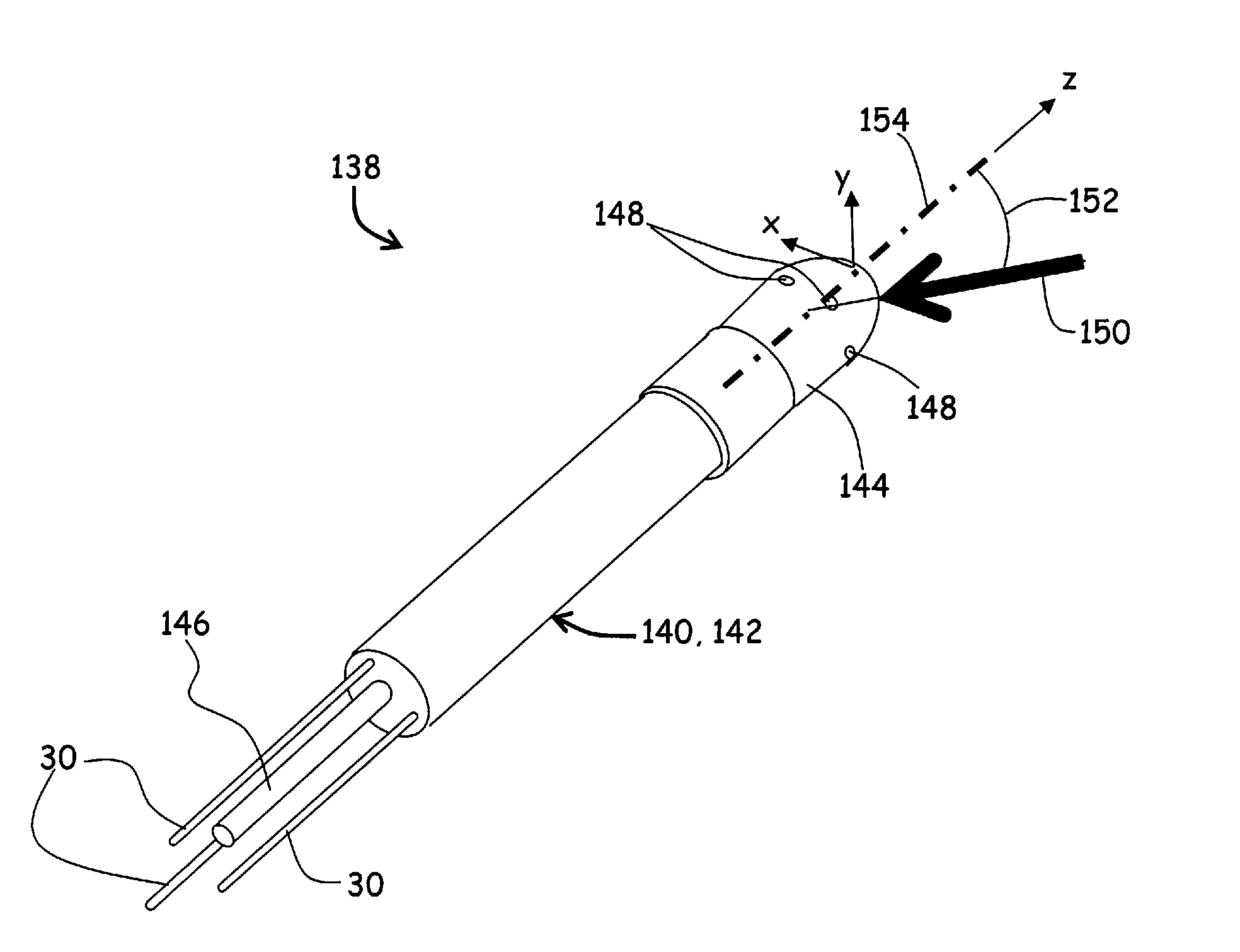
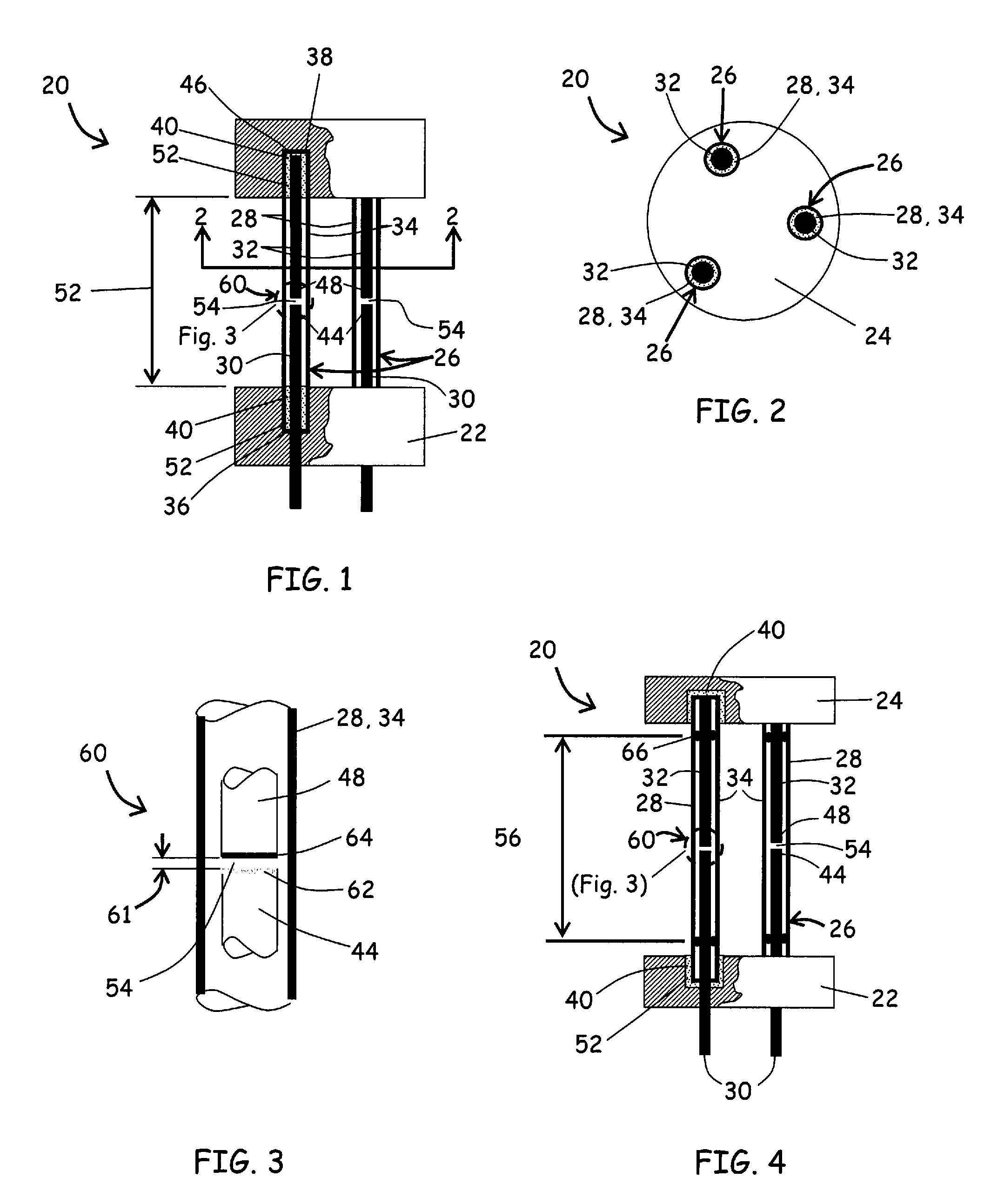
[0057]Referring to FIGS. 1 through 3, a strain sensor assembly 20 is depicted according to an embodiment of the invention. In this embodiment, a proximal or base portion 22 and a distal or head portion 24 are separated by a trio of strain sensing elements 26. Each strain sensing element 26 includes the standoff member 28, a transmitting element 30 and a reflecting element 32. Each standoff member 28 is comprised of a hollow tube 34 having a proximal end 36 and a distal end 38 that are disposed in sockets 40 formed in the proximal and distal portions 22 and 24.

[0058]In this embodiment, the transmitting element 30 of each strain sensing element 26 includes a free end 44 that extends partway into the hollow tube 34. The reflecting element 32 includes an anchor end 46 and a free end 48 and is housed within the hollow tube 34 opposite the transmitting element 30.

[0059]The transmitting and reflecting elements 38 and 42 are each secured to the hollow tube 36 with a potting 52 and are posit...


PUM


Abstract

A touch sensing catheter having a strain sensor assembly that may resolve the magnitude and direction of a force exerted on a distal extremity of the catheter, the strain sensor assembly being substantially insensitive to bulk temperature changes. A deformable structure having a plurality of optical fibers associated therewith that are strained by the imposition of a contact force transferred thereto. The optical fibers cooperate with the deformable structure to effect variable gap interferometers, such as Fabry-Perot resonators, that vary in operative length when a force is exerted on the deformable structure. The strain sensor assembly is rendered insensitive to bulk temperature changes by matching the coefficient of thermal expansion of the deformable body with that of the optical fibers. The strain sensor assembly may also be configured to mitigate the effects of thermal gradients using various thermal isolation techniques.

Description

FIELD OF THE INVENTION[0001]The disclosed invention relates generally to force sensing devices capable of resolving the magnitude and direction of a force vector. More specifically, the invention relates to a force sensing tip to aid in the positioning of catheters used in humans or animals, or for serving as feedback elements in robotic surgical systems.BACKGROUND[0002]For many years, exploration and treatment of various organs or vessels has been possible using catheter-based diagnostic and treatment systems. Such catheters are introduced through a vessel leading to the cavity of the organ to be explored or treated or alternatively may be introduced directly through an incision made in the wall of the organ. In this manner, the patient avoids the trauma and extended recuperation times typically associated with open surgical procedures.[0003]To provide effective diagnosis or therapy, it is frequently necessary to first map the zone to be treated with great precision. Such mapping m...

Claims


Application Information

Patent Timeline
IPC IPC(8): A61M31/00A61F5/44
CPCA61B5/6885A61B18/1492A61B19/46A61B2017/00057A61B2017/00084A61B2019/464A61B2218/002A61M2025/0002A61B2090/064A61B90/06A61B5/6852A61B2562/0266
Inventor LEO, GIOVANNIAEBY, NICOLASINAUDI, DANIELE
Owner ST JUDE MEDICAL INT HLDG SARL
Why Eureka
Try Eureka