A cable laying device with corner function

A cable laying and functional technology, used in cable laying equipment, transportation and packaging, transportation of filamentous materials, etc., can solve the problems of heavy cable weight, easy to wear cable insulation layer, limited cable trench space, etc. Small, increased footprint, small volume

Active Publication Date: 2016-09-07
STATE GRID CORP OF CHINA +1
View PDF4 Cites 0 Cited by
  • Summary
  • Abstract
  • Description
  • Claims
  • Application Information

AI Technical Summary

Problems solved by technology

[0002] At present, in power supply companies, cables are widely used in power systems to realize power transmission. The most effective and safe transportation method is to bury cables in cable trenches. However, when cables are laid in cable trenches, manual laying is often required. The weight of the cable is high, the laying difficulty is high, and the space in the cable trench is limited, the movement is inconvenient, the manual completion is time-consuming and laborious, the efficiency is low, and due to the manual dragging of the cable, it is easy to wear the insulation layer of the cable, burying hidden dangers for safety
In order to improve laying efficiency, those skilled in the art have invented a series of laying machines, but most of them need to be driven by motors. When the transmission cable is accidentally stuck, the motor cannot form self-protection, which is easy to damage the motor and cause a fire. In addition, the above laying machines cannot Complete the function of turning corners at any angle, which is very inconvenient to use

Method used


Image

  • A cable laying device with corner function
  • A cable laying device with corner function
  • A cable laying device with corner function

Examples


Embodiment Construction

[0021] The following will be combined with Figure 1-5 The present invention will be described in further detail.

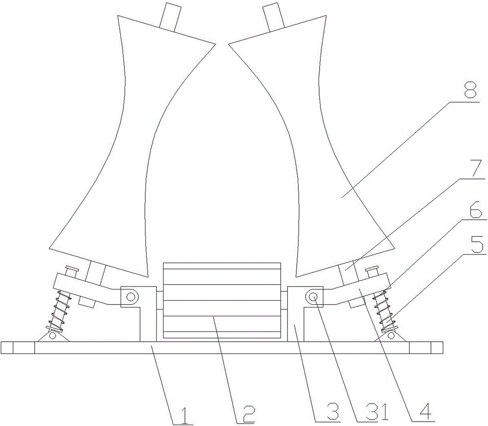
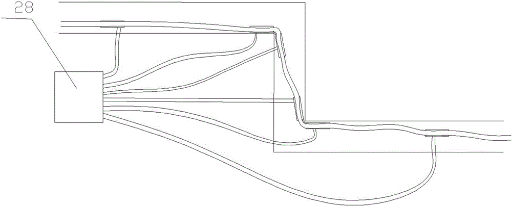
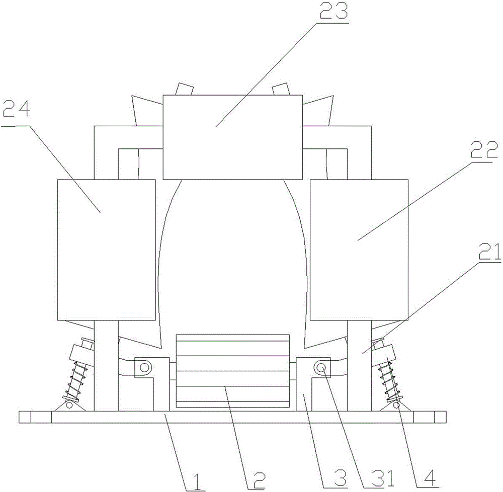
[0022] as attached Figure 1-4 As shown, a high-efficiency cable laying device with a corner function includes two laying bodies hinged by steel plates 25, and the two ends of the steel plate 25 are respectively connected to the two laying bodies through hinge shafts 26, and the steel plates 25 are provided with There is runner 27.

[0023] The laying body includes a base 1, a conveyor belt 2, a fixed frame 3, a pressure wheel 8 and a connecting rod 5 with a compression spring 6, the conveyor belt 2 is fixed on the base 1, and the fixed frame 3 is fixed on the On both sides of the conveyor belt 2, the connecting rod 5 is hinged on the base 1 and is located outside the fixed frame 3. The fixed frame 3 is hinged with a connecting plate 4 through a rotating shaft 31, and the other of the connecting plate 4 One end is sleeved on the outside of the connecting rod 5...


PUM


Abstract

The invention relates to a high-efficiency cable laying device with corner function, which includes two laying bodies through steel plate hinges, and the laying bodies are driven by a hydraulic drive machine. The equipment of the present invention is small in size and is suitable for use in cable trenches with small spaces. Since it includes two laying bodies through steel plate hinges, the angle can be adjusted at corners at will to realize the function of adjusting any angle.

Description

technical field [0001] The invention relates to the technical field of cable laying and transportation machines, in particular to an efficient cable laying device with corner function. Background technique [0002] At present, in power supply companies, cables are widely used in power systems to realize power transmission. The most effective and safe transportation method is to bury cables in cable trenches. However, when cables are laid in cable trenches, manual laying is often required. The weight of the cable is high, the laying difficulty is high, and the space in the cable trench is limited, the movement is inconvenient, the manual completion is time-consuming and laborious, the efficiency is low, and due to the manual dragging of the cable, it is easy to wear the insulation layer of the cable, burying hidden dangers for safety . In order to improve laying efficiency, those skilled in the art have invented a series of laying machines, but most of them need to be driven...

Claims


Application Information

Patent Timeline
Patent Type & Authority Patents(China)
IPC IPC(8): H02G1/06B65H51/14B65H57/14
Inventor 王金忠张立朋
Owner STATE GRID CORP OF CHINA
Why Eureka
Try Eureka