Medium or high voltage electrical equipment control device and method of controlling a medium or high voltage electrical equipment control device

A control device and substation technology, applied in the field of medium-voltage or high-voltage substations, and controlling medium-voltage or high-voltage substations, which can solve the problems of difficulty in constructing and developing mechanical locking mechanisms, expensive manual control and safety systems, and difficulty in on-site implementation.

Active Publication Date: 2008-02-06
AREVA T&D
View PDF0 Cites 6 Cited by
  • Summary
  • Abstract
  • Description
  • Claims
  • Application Information

AI Technical Summary

Problems solved by technology

[0014] It is difficult to construct and develop such a mechanical locking mechanism
[0015] Manual controls and safety systems are expensive and, in addition, difficult to implement in the field

Method used


Image

  • Medium or high voltage electrical equipment control device and method of controlling a medium or high voltage electrical equipment control device
  • Medium or high voltage electrical equipment control device and method of controlling a medium or high voltage electrical equipment control device
  • Medium or high voltage electrical equipment control device and method of controlling a medium or high voltage electrical equipment control device

Examples


Embodiment Construction

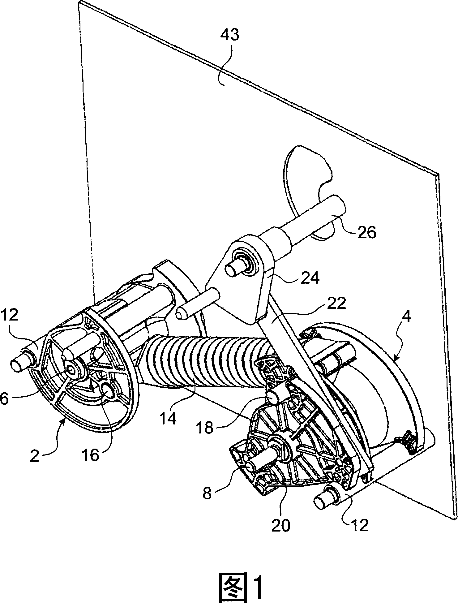
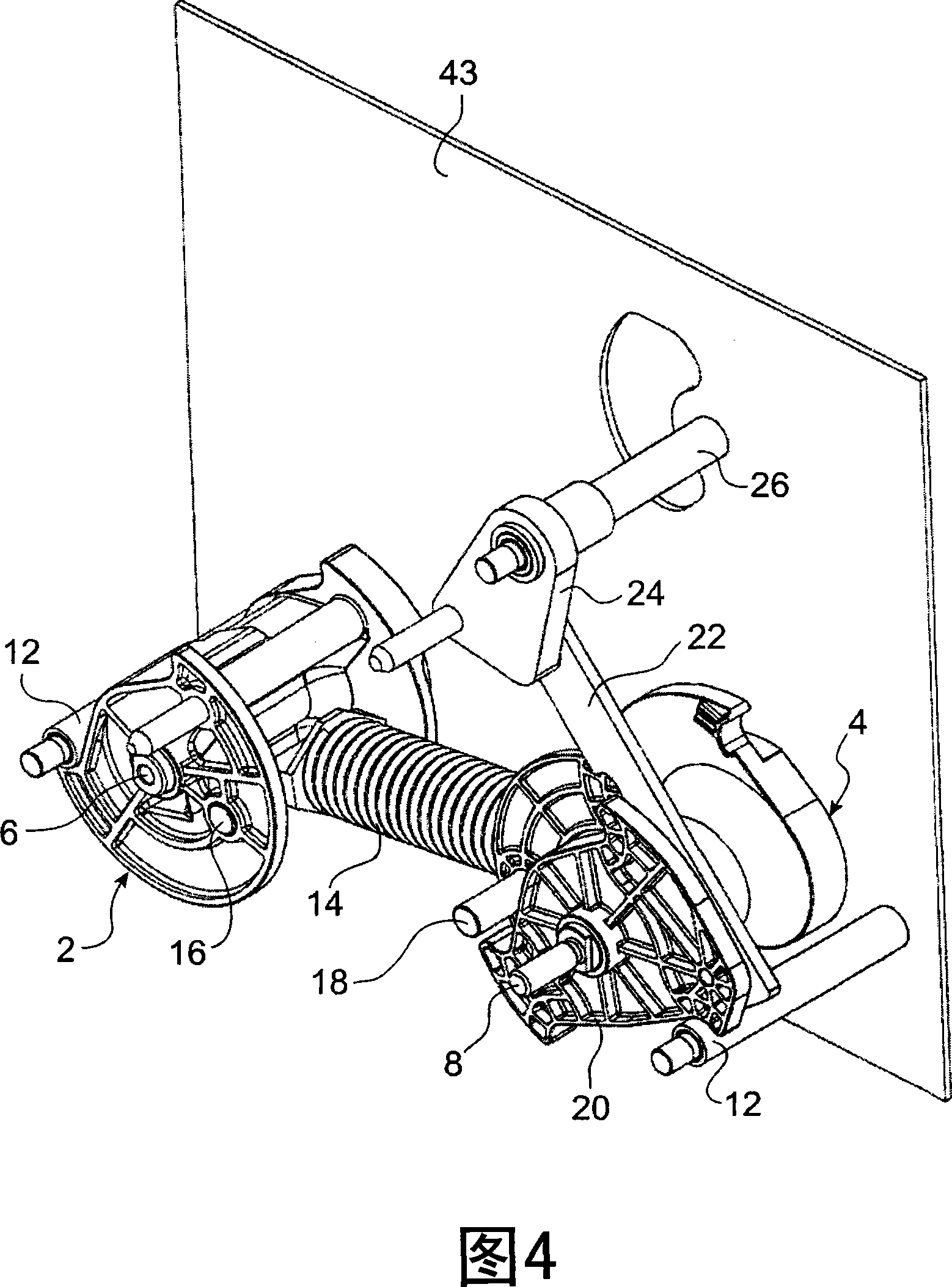
[0072] Figure 1 shows a commutator-type spring-loaded control mechanism for a medium voltage substation to which the invention is applicable.

[0073] In FIG. 1 , reference numeral 2 refers to a grounded breaker commutator, and reference numeral 4 refers to a switching commutator. The commutator 2 is rotatably mounted on the ground breaker shaft 6 and the commutator 4 is rotatably mounted on the switch shaft 8 . Shafts 6 and 8 are made of metal. They are mounted between a front plate 44 (Fig. 7A) and a rear plate 43, wherein the front plate is mounted parallel to the rear plate. A rod 12 is installed between the front and rear panels. The function of the rod is to limit the rotation of commutator 2 and commutator 4 . A spring 14 is installed between the commutators 2 and 4 . One end of the spring 14 is pivotally mounted on the commutator 2 so as to pivot about the grounding breaker spring pin 16, and the other end of said spring is pivotally mounted on the commutator 4 suc...


PUM


Abstract

The invention especially relates to a motor driven control device for controlling a switch connected with ground breaker, control mechanism of the said switch, and control mechanism of the said ground breaker. The motor and gear unit (49) are composed of motor and gear case(48), and the said gear case(48) comprises at least one first gear (52) jogged with the axis of the motor and at least one second gear (50) jogged with the said control mechanism and a device for transferring the rotation from a first gear to the second gear, selected from the first gear, the second gear (50) and the said device for transferring the rotation from a first gear to the second gear, at least one component of gear case(48) suited to be taken off and laid back in place, to interrupt or accordingly rebuild a power driven link from the said motor (46) to said control mechanism. The gear (50) is took out to bare the hole, so that the said switch can be manually controlled.

Description

technical field [0001] The invention relates to a control device for controlling a medium or high voltage substation and to a medium or high voltage substation comprising said control device. The invention also relates to a method of controlling a medium voltage or high voltage substation. Background technique [0002] A distribution substation, such as a medium voltage substation, is composed of two components: a first switch, which passes current through the substation, or interrupts current flow through the substation; and a second switch, which is used to Connect the cables from the substation to a potential of 0 volts (V). The second switch is used to protect the operator, for example, when the operator is performing maintenance. [0003] The components are controlled by a spring loaded control mechanism having a tumbler or cam and moving through dead center. This type of mechanism is mainly used in medium voltage substations. However, such mechanisms are also used ...

Claims


Application Information

Patent Timeline
Patent Type & Authority Applications(China)
IPC IPC(8): H01H31/10H01H3/26H01H9/26H01H33/36
CPCH01H3/40H01H31/003H01H31/10H01H3/26H01H3/227H01H2300/024
Inventor D·皮科斯H·戈捷
Owner AREVA T&D
Why Eureka
Try Eureka