Fuse wire circuit
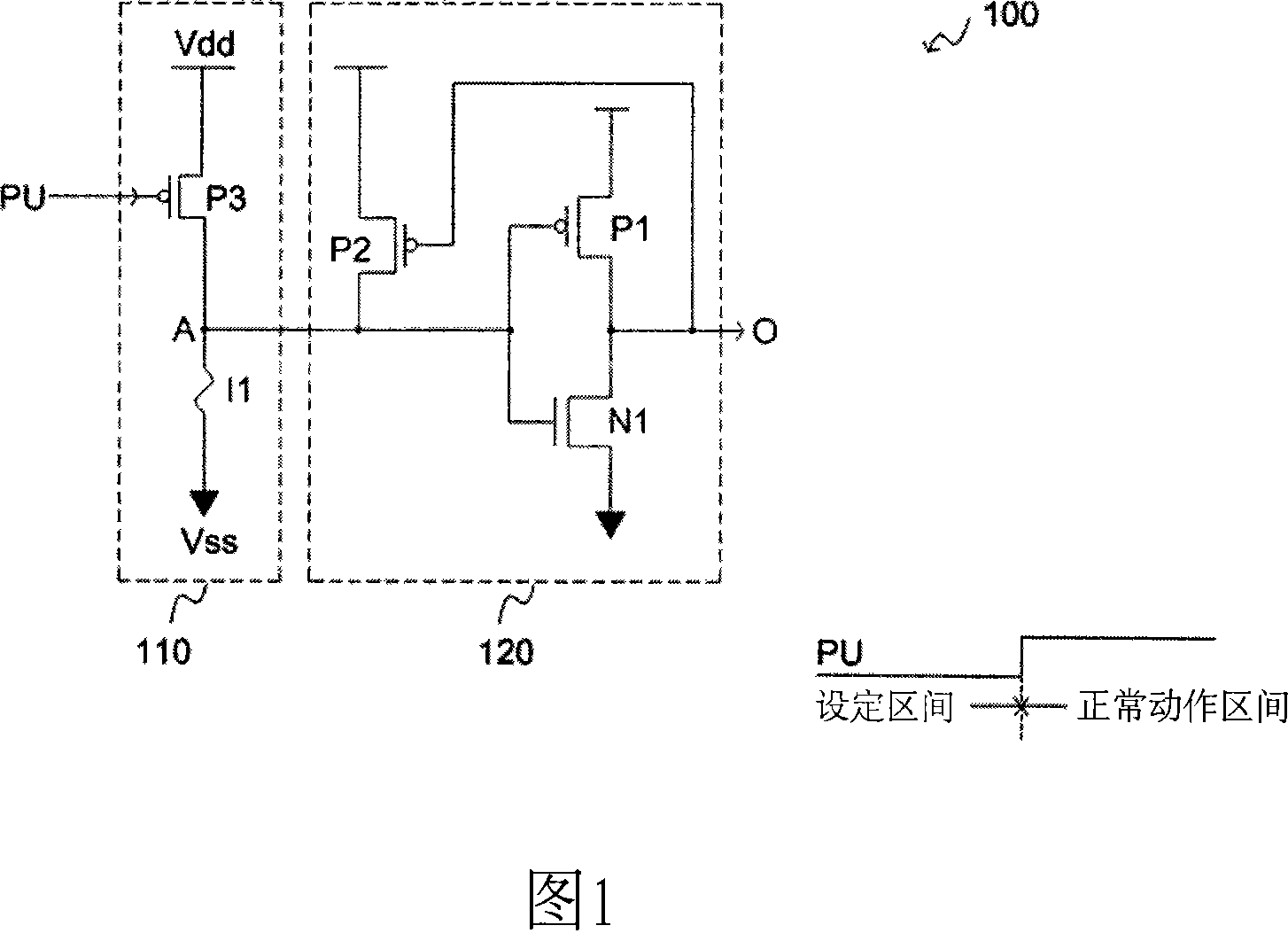
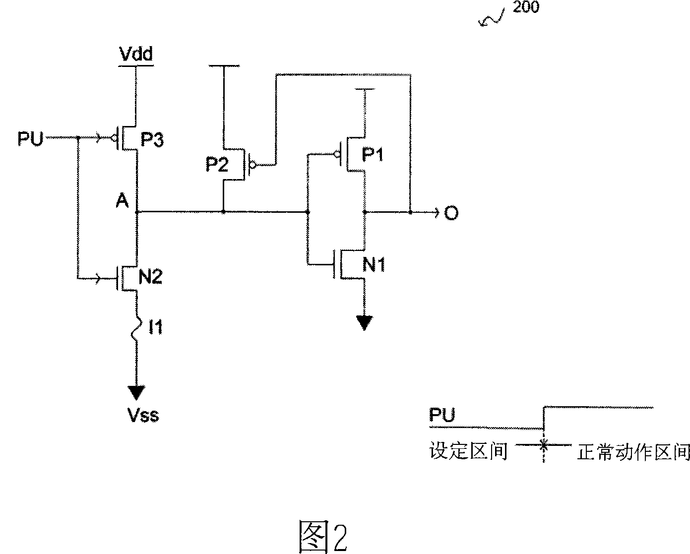
A fuse and circuit technology, applied in the direction of electrical components, electric pulse generation, static memory, etc., can solve the problems of manufacturing cost and no solution proposed by the fuse circuit 200
- Summary
- Abstract
- Description
- Claims
- Application Information
AI Technical Summary
Problems solved by technology
Method used
Image
Examples
Embodiment Construction
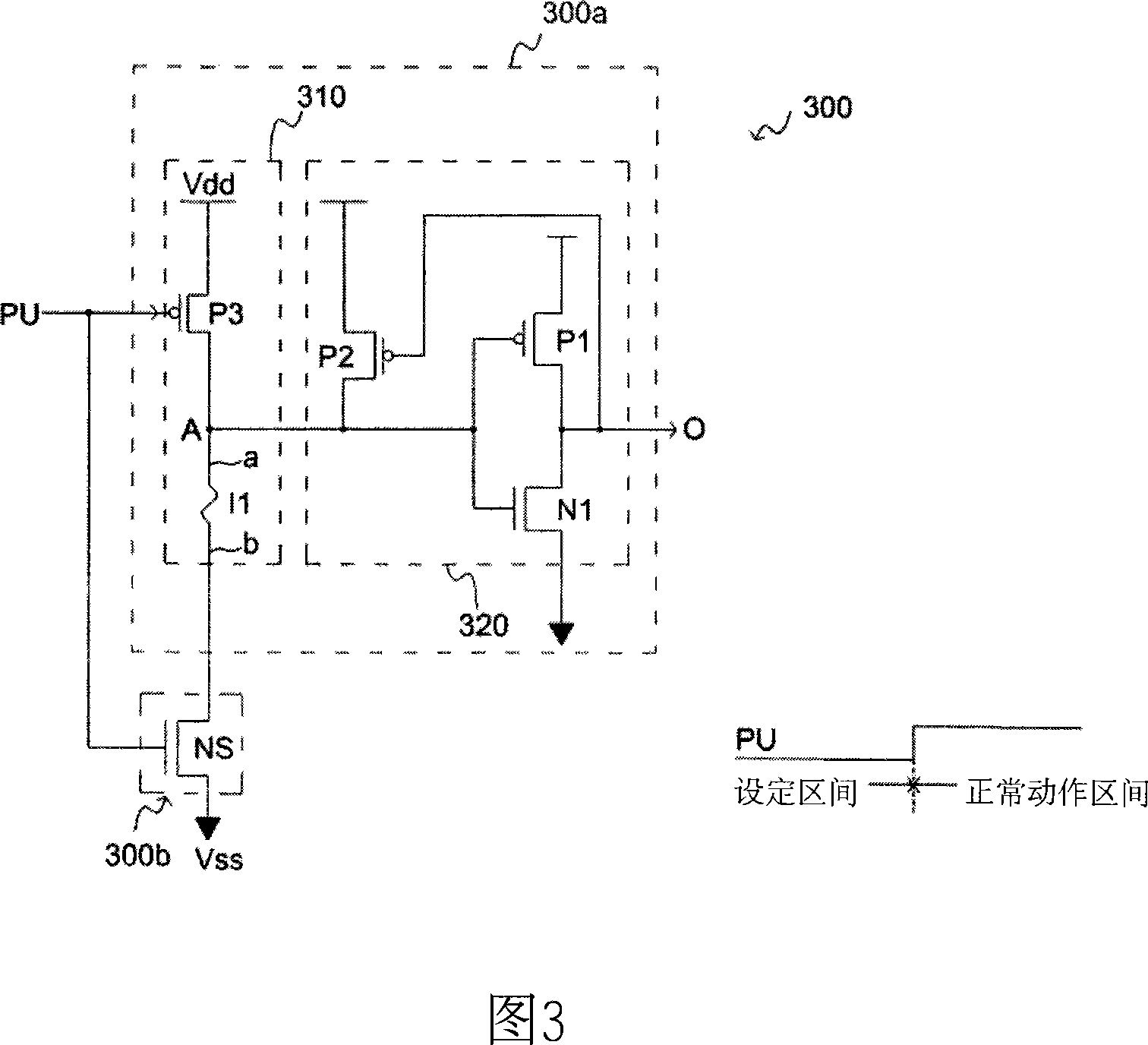
[0040] image 3 It is a schematic diagram of a first embodiment of the fuse circuit 300 of the present invention. Such as image 3 As shown, the fuse circuit 300 includes a fuse circuit unit 300a and a current blocking module 300b. The fuse circuit 300 is used to output an output signal O according to an initial setting signal PU, and the initial setting signal PU includes a setting interval and a normal operation interval.
[0041] The fuse circuit unit 300 a includes a voltage building module 310 and a latch 320 . The voltage establishing module 310 is used for establishing a voltage potential on the node A according to the blown state of the fuse I1 which can be blown selectively. The fuse I1 has a first terminal a and a second terminal b; and the latch 320 then performs a latch operation on the voltage potential established on the node A to generate an output signal. Wherein, it can be seen from the figure that the connection of the transistors P1 and N1 of the latch 3...
PUM
 Abstract
Description
Claims
Application Information
 - R&D
- Intellectual Property
- Life Sciences
- Materials
- Tech Scout
- Unparalleled Data Quality
- Higher Quality Content
- 60% Fewer Hallucinations
Browse by: Latest US Patents, China's latest patents, Technical Efficacy Thesaurus, Application Domain, Technology Topic, Popular Technical Reports.
© 2025 PatSnap. All rights reserved.Legal|Privacy policy|Modern Slavery Act Transparency Statement|Sitemap|About US| Contact US: help@patsnap.com


