Method for improving residual shadow phenomena

A phenomenon and afterimage technology, applied in color TV parts, TV system parts, TVs, etc., can solve the problems of liquid crystal molecules 11 not turning immediately, afterimages, and release of charged ions, so as to improve the afterimages. effect of phenomenon

Inactive Publication Date: 2008-02-13
CHUNGHWA PICTURE TUBES LTD
View PDF0 Cites 1 Cited by
  • Summary
  • Abstract
  • Description
  • Claims
  • Application Information

AI Technical Summary

Problems solved by technology

So when the frame is switched, the charged ions cannot be released from the derivative capacitor in time
So that the liquid crystal molecules 11 can not immediately turn to the corresponding angle, resulting in afterimage phenomenon
When the existing li

Method used


Image

  • Method for improving residual shadow phenomena
  • Method for improving residual shadow phenomena
  • Method for improving residual shadow phenomena

Examples


Embodiment Construction

[0020] FIG. 4 is a schematic frame diagram of implementing a method for improving afterimage phenomenon according to an embodiment of the present invention. The frames T41-T44 represent frames of different time sequences, and the scan line positions G1-Gn represent positions of different scan lines. The way to improve image sticking is to insert corresponding first gray scale lines in at least one scan line position in one frame, and insert a corresponding number of second gray scale lines in at least one scan line position in the next frame. In this embodiment, the first grayscale line and the second grayscale line are respectively a black line and a midtone gray line, that is, a black line and a midtone gray line are alternately inserted into the frame. First, a black line is inserted at the scan line position G1 of frame T41 (the black line is represented by parallel straight lines from top to bottom), and then a midtone gray line is inserted at the scan line position G1 of...


PUM


Abstract

The present invention discloses a method for improving remnant trace, which includes: firstly inserting at least one first gray-scale line in a frame at the position of the corresponding scalar scanning line, and inserting at least one second gray-scale line in a frame at the position of the corresponding scalar scanning line. A pixel unit has no remnant trace phenomena appeared when converting the pictures because of long-time displaying of the same picture, in virtue of the whole frame inserting the gray-scale line to different positions according to time sequence. The present invention can improve the remnant trace phenomena of the electronic frames and the LCDs, so the display can be more fitful for human visual demand and promote the displaying quality of the display.

Description

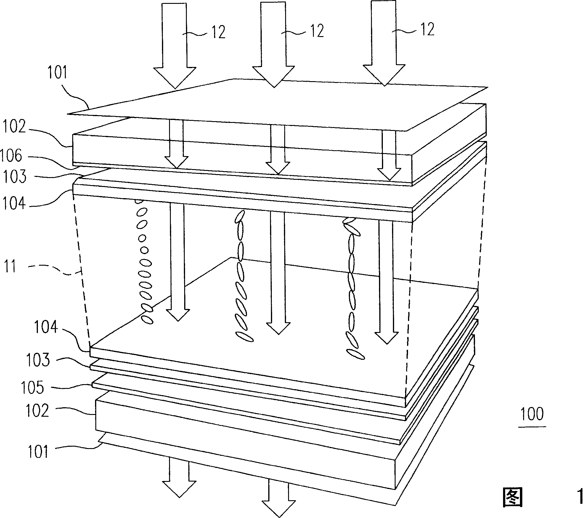
technical field [0001] The present invention relates to a method for improving the image sticking phenomenon, and particularly relates to a method for improving the image sticking phenomenon by inserting grayscale lines in time sequence. Background technique [0002] FIG. 1 is an internal structural diagram of a conventional liquid crystal display 100 . The LCD 100 includes a polarizer 101 , a glass substrate 102 , an Indium Tin Oxide (ITO) film 103 , an alignment film 104 , a color filter 105 , a thin film transistor (TFT) 106 and liquid crystal molecules 11 . The thin film transistor 106 and the indium tin oxide thin film 103 apply voltage to the liquid crystal molecules 11, and the alignment film 104 fixes the liquid crystal molecules 11 in a certain direction, and the color filter 105 filters the light 12 out of the three primary colors of red, blue, and green light, while the polarized light Sheet 101 only allows light in and out of certain directions. The light 12 ca...

Claims


Application Information

Patent Timeline
IPC IPC(8): H04N5/202
Inventor 林奕岚叶国超刘祥伦
Owner CHUNGHWA PICTURE TUBES LTD
Why Eureka
Try Eureka