Assembled ball goal middle bottom beam and column mounting structure

An installation structure and assembled technology, applied in the direction of ball games, connecting components, sports accessories, etc., can solve the problems of poor stability and troublesome positioning of the goal, and achieve the effect of convenient installation and positioning and good stability

Inactive Publication Date: 2008-02-20
JIANGSU JINLING SPORTS EQUIP
View PDF0 Cites 5 Cited by
  • Summary
  • Abstract
  • Description
  • Claims
  • Application Information

AI Technical Summary

Problems solved by technology

The installation structure of the crossbeam and the column, on the one hand: it makes the positioning of the connecting piece 3 and the upp

Method used


Image

  • Assembled ball goal middle bottom beam and column mounting structure
  • Assembled ball goal middle bottom beam and column mounting structure
  • Assembled ball goal middle bottom beam and column mounting structure

Examples


Example Embodiment

[0018] The specific embodiments of the present invention will be described in detail below with reference to the accompanying drawings.

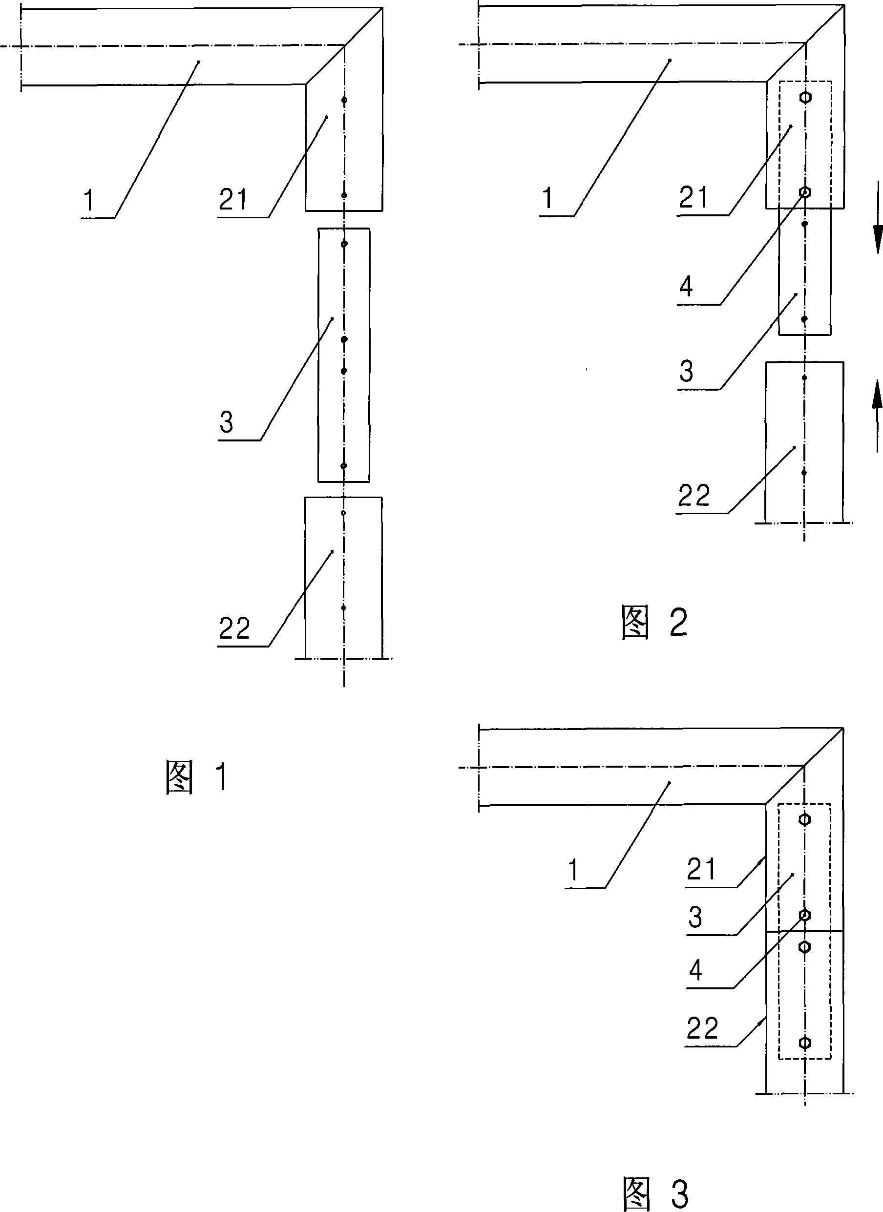
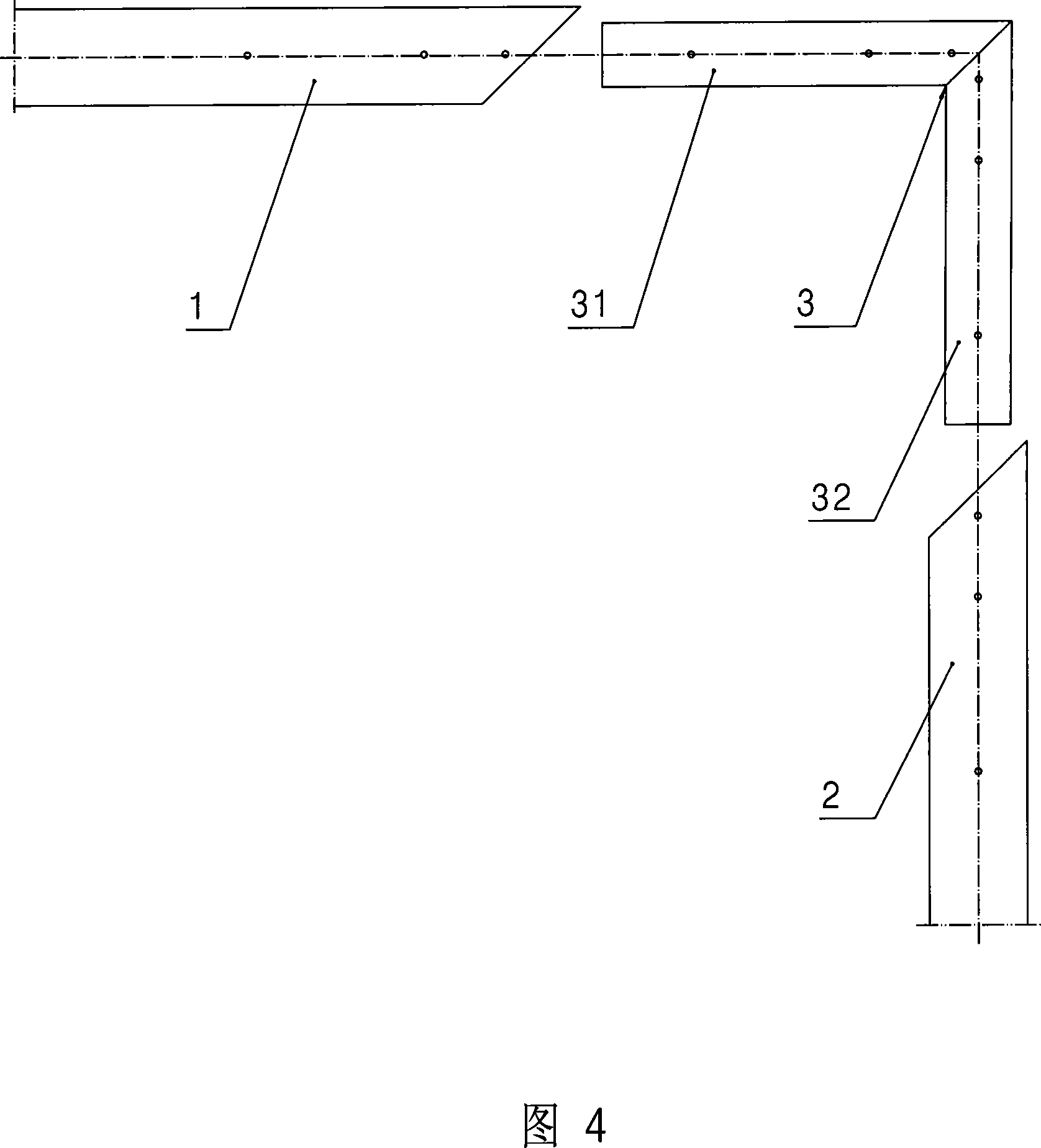
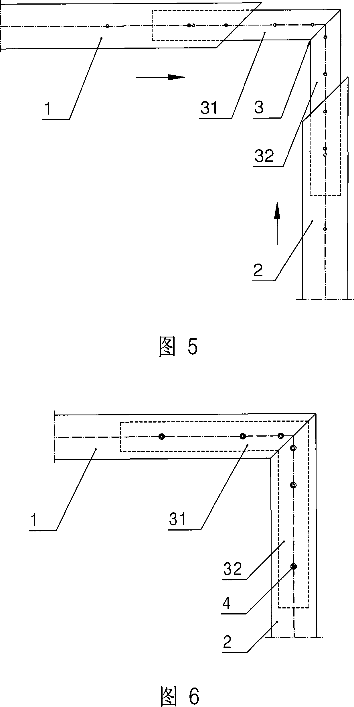
[0019] As shown in Figure 4, the installation structure of the crossbeam and column in the assembled goal of the present invention includes: a corner connector 3, which is composed of a horizontal plug-in 31 and a vertical plug-in 32 that are perpendicular to each other, and the horizontal plug-in 31 is embedded It is arranged in the connecting cavity at the end of the beam 1 and fixed by bolts 4, and the vertical insert 32 is embedded in the connecting cavity on the top of the column 2 and fixed by bolts 4. In this embodiment, both end faces of the cross beam 1 and the top end of the column 2 are inclined planes with an angle of 45°, so that the cross beam 1 and the column 2 can be completely matched after being assembled, and the corner connector 3 is completely covered inside.

[0020] When the beam 1 and the column 2 of the present invention...


PUM


Abstract

The invention discloses a beam and an upright pillar mounting structure in an assembling typed goal which is convenient to be assembled and can improve the stability of the goal, the invention comprises an angle connecting piece which consists of a horizontal plug-in and a vertical plug-in; the horizontal plug-in is embedded in a connecting cavity at the end of the beam and is connected with the beam; the vertical plug-in is embedded in a connecting cavity at the top of the upright pillar and is connected with the upright pillar. The location and the installation of the beam and the upright pillar are very simple; and the goal stability after assembling is good.

Description

technical field [0001] The invention relates to an assembled goal, in particular to the installation structure of the beam and the column in the assembled goal. Background technique [0002] As we all know, in order to facilitate transportation, all kinds of larger goals (such as football goals, handball goals, hockey goals, etc.) are assembled. Usually, the assembled goals include: a beam, two columns, two bottom Side bars, two supporting frames and corresponding connecting pieces, wherein: the crossbeam is arranged on the top of the two columns. As shown in FIG. 1 , the upright column is divided into upper and lower sections, the upper section 21 is fixed with the crossbeam 1 , and the ends of the upper section 21 and the lower section 22 of the upright column are provided with connecting chambers matched with the connector 3 . When the upper section 21 and the lower section 22 of the column are assembled, at first the top of the straight connector 3 is plugged into the c...

Claims


Application Information

Patent Timeline
IPC IPC(8): A63B63/00F16B12/00
Inventor 李春荣
Owner JIANGSU JINLING SPORTS EQUIP
Why Eureka
Try Eureka