An elevator landing door positioning device

A door positioning and elevator floor technology, which is applied in the field of elevator landing door positioning devices, can solve the problems of long time-consuming positioning and installation, labor cost, and low assembly accuracy, and achieve the effects of improving installation efficiency, reducing labor costs, and improving accuracy

Active Publication Date: 2021-01-19
广东恩晟电梯有限公司
View PDF8 Cites 0 Cited by
  • Summary
  • Abstract
  • Description
  • Claims
  • Application Information

AI Technical Summary

Problems solved by technology

Among them, the existing elevator landing door positioning installation is to manually install and position the elevator landing door panel relative to the processing station through screws or positioning pins, which not only takes a long time for positioning and installation, but also has low assembly accuracy and consumes a lot of labor costs.

Method used


Image

  • An elevator landing door positioning device
  • An elevator landing door positioning device
  • An elevator landing door positioning device

Examples


Embodiment 1

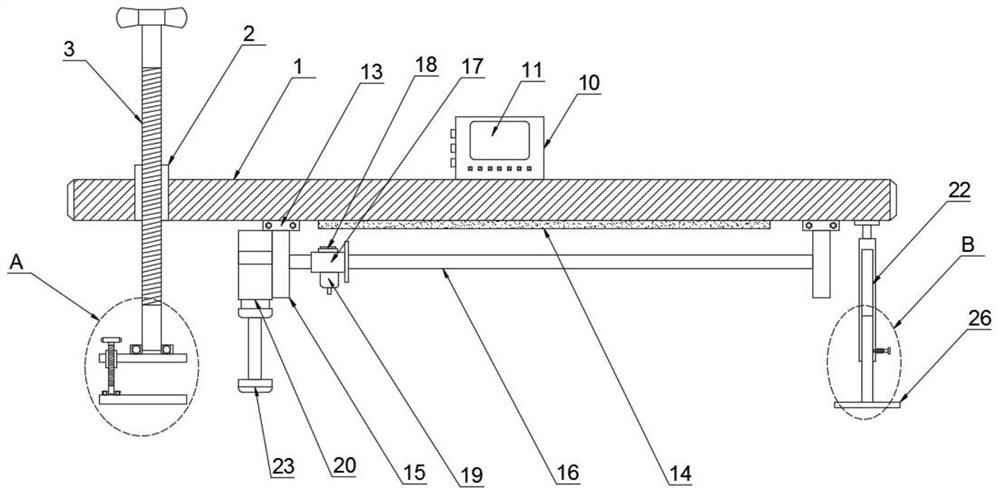
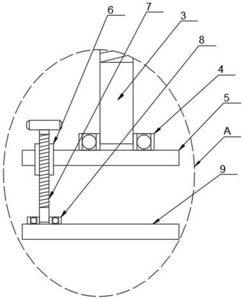
[0023]Such asFigure 1-4An elevator landing door positioning device shown includes a worktable 1 on which a first threaded tube 2 is provided, and a first threaded rod 3 penetrates through the first threaded tube 2, so The bottom end of the first threaded rod 3 is provided with a first bearing 4, the bottom of the first bearing 4 is provided with a first splint 5, and a second threaded tube 6 penetrates through the first splint 5, and the second thread A second threaded rod 7 penetrates through the tube 6, a second bearing 8 is provided at the bottom end of the second threaded rod 7, a second clamping plate 9 is provided at the bottom of the second bearing 8, and the worktable 1 is provided There is a control box 10, the control box 10 is provided with a display screen 11, the control box 10 is provided with a microprocessor 12 inside, and the bottom of the workbench 1 is provided with a mounting block 13, the number of the mounting block 13 The two mounting blocks 13 are provided wi...

Embodiment 2

[0026]Such asFigure 1-4An elevator landing door positioning device shown includes a worktable 1 on which a first threaded tube 2 is provided, and a first threaded rod 3 penetrates through the first threaded tube 2, so The bottom end of the first threaded rod 3 is provided with a first bearing 4, the bottom of the first bearing 4 is provided with a first splint 5, and a second threaded tube 6 penetrates through the first splint 5, and the second thread A second threaded rod 7 penetrates through the tube 6, a second bearing 8 is provided at the bottom end of the second threaded rod 7, a second clamping plate 9 is provided at the bottom of the second bearing 8, and the worktable 1 is provided There is a control box 10, the control box 10 is provided with a display screen 11, the control box 10 is provided with a microprocessor 12 inside, and the bottom of the workbench 1 is provided with a mounting block 13, the number of the mounting block 13 The two mounting blocks 13 are provided wi...


PUM


Abstract

The invention discloses an elevator landing door positioning apparatus, which comprises a working table plate, wherein the working table plate is provided with a first threaded pipe, a first threadedrod penetrates through the interior of the first threaded pipe, the bottom end of the first threaded rod is provided with a first bearing, a first clamping plate is arranged on the bottom portion of the first bearing, a second threaded pipe penetrates through the first clamping plate, a second threaded rod penetrates through the interior of the second threaded pipe, a second bearing is arranged onthe bottom end of the second threaded rod, a second clamping plate is arranged on the bottom portion of the second bearing, a control box is arranged on the working table plate, and is provided witha display screen, a micro processor is arranged inside the control box, two installing blocks are arranged on the bottom portion of the working table plate, and a reflecting mirror is arranged betweenthe two installing blocks. Compared with the traditional manual positioning mode, the apparatus of the invention has advantages of improved positioning precision, reduced labor cost and improved installation efficiency.

Description

Technical field[0001]The invention relates to the technical field of elevator equipment, in particular to an elevator landing door positioning device.Background technique[0002]An elevator refers to a permanent transportation device that serves several specific floors in a building, and its car runs on at least two rows of rigid rails that are perpendicular to the horizontal plane or whose inclination angle to the plumb line is less than 15°. The vertical elevator has a car that runs between at least two rows of vertical or rigid guide rails with an inclination angle of less than 15°. The size and structure of the car are convenient for passengers to enter and exit or load and unload cargo.[0003]Modern elevators are mainly composed of traction machines (winches), guide rails, counterweight devices, safety devices (such as speed limiters, safety gears and buffers, etc.), signal control systems, cars and hall doors. These parts are respectively installed in the shaft and machine room o...

Claims


Application Information

Patent Timeline
Patent Type & Authority Patents(China)
IPC IPC(8): G01B11/14
CPCG01B11/14
Inventor 胡宏宝刘经高罗丽龙
Owner 广东恩晟电梯有限公司
Why Eureka
Try Eureka