Clamping fastener

A technology of a clip and a limit wall, applied in the field of clips, can solve the problems of cumbersome and many operation procedures, and achieve the effects of simple overall structure, convenient manufacture, convenient and quick installation and positioning

Active Publication Date: 2016-04-20
苏州东山昆拓热控系统有限公司
View PDF5 Cites 0 Cited by
  • Summary
  • Abstract
  • Description
  • Claims
  • Application Information

AI Technical Summary

Problems solved by technology

However, this kind of structure has many operating procedures in t

Method used


Image

  • Clamping fastener
  • Clamping fastener
  • Clamping fastener

Examples


Example Embodiment

[0020] The present invention will be described in detail below with reference to the various embodiments shown in the accompanying drawings. However, these embodiments do not limit the present invention, and structural, method, or functional changes made by those skilled in the art according to these embodiments are all included in the protection scope of the present invention.

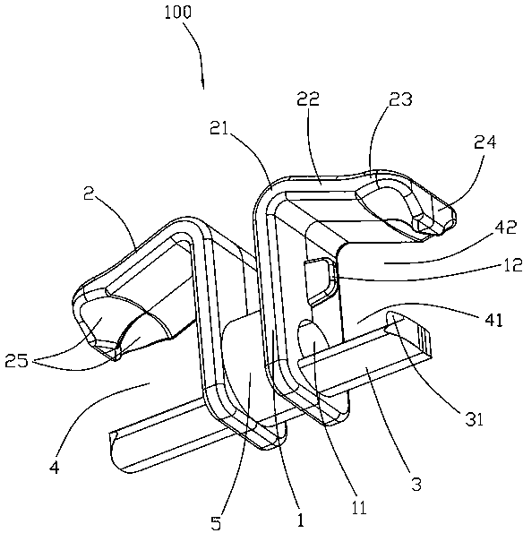
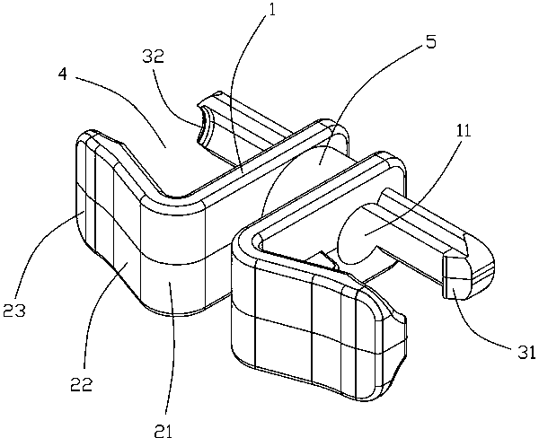
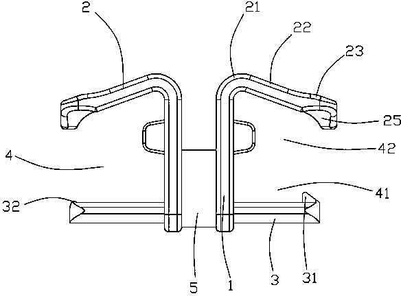
[0021] Please refer to Figure 1 to Figure 4 Shown is a preferred embodiment of the fastener 100 of the present invention. The fastener 100 of the present invention includes a positioning wall 1, a clamping wall 2 bent and extended from the positioning wall 1, a limiting wall 3 disposed opposite the clamping wall 2 and connected with the positioning wall 1, formed on the positioning wall 1, The accommodating cavity 4 between the clamping wall 2 and the limiting wall 3 . The positioning wall 1 has a positioning hole 11 disposed therethrough along the extending direction of the limiting wall 3 , and t...


PUM


Abstract

The invention provides a clamping fastener. The clamping fastener comprises a positioning wall, a clamping wall bent to extend from the positioning wall, a limiting wall opposite to the clamping wall and connected with the positioning wall, and accommodating cavities formed among the positioning wall, the clamping wall and the limiting wall. The positioning wall has a positioning hole penetrating through the extending direction of the limiting wall. The positioning hole is near the limiting wall. The accommodating cavities have a first accommodating cavity communicated with the positioning hole in the penetrating direction of the positioning hole, and a second accommodating cavity formed between the first accommodating cavity and the clamping wall.

Description

technical field [0001] The invention relates to a buckle, in particular to a buckle which can be used on the pipeline of the refrigeration system of an air conditioner. Background technique [0002] Air conditioners are usually used to adjust parameters such as temperature, humidity, cleanliness, and air velocity in a space area to meet the requirements of human comfort or process. At present, in the design of the refrigeration pipeline of the air conditioner, the shape of the temperature-sensing probe used to sense the temperature of the refrigeration system pipeline is generally cylindrical. When assembling, it is necessary to weld a length equal to the length of the temperature-sensing probe on the surface of the copper tube. Circular sleeve, then insert the spring fixing card into the sleeve first, and then insert the temperature sensor, the temperature sensor will be in firm contact with the sleeve under the action of elastic force. When working, the temperature-sensin...

Claims


Application Information

Patent Timeline
IPC IPC(8): F24F13/00
Inventor 胡晴雯
Owner 苏州东山昆拓热控系统有限公司
Why Eureka
Try Eureka