
Pasting machine

The technology of a plastering machine and a lifting mechanism, which is applied in the directions of construction and building structure, can solve the problems of inability to plaster the wall, small working range, uneven plastering layer, etc., and achieves good plastering quality and application scope. Wide and easy-to-operate effects

Inactive Publication Date: 2008-02-20
邓国飞
View PDF1 Cites 14 Cited by
  • Summary
  • Abstract
  • Description
  • Claims
  • Application Information

AI Technical Summary

Problems solved by technology

When the existing plastering machine is plastering the wall, the working range is small, and the wall cannot be fully plastered. As disclosed in the Chinese Patent Gazette, the patent No. 93219089.8 is called "vibration plastering machine" , when plastering the wall, it can only be used for a large area of ​​the wall, and it is not suitable for plastering the internal corners, external corners, ceilings, window sills, stairs, columns and other parts of the wall, and the plastering of the ash The layer is uneven and irregular, and finally a lot of post-processing work is required manually, which is time-consuming and labor-intensive and is not conducive to the improvement of work efficiency

Method used


Image

  • Pasting machine
  • Pasting machine
  • Pasting machine

Examples


Embodiment 1

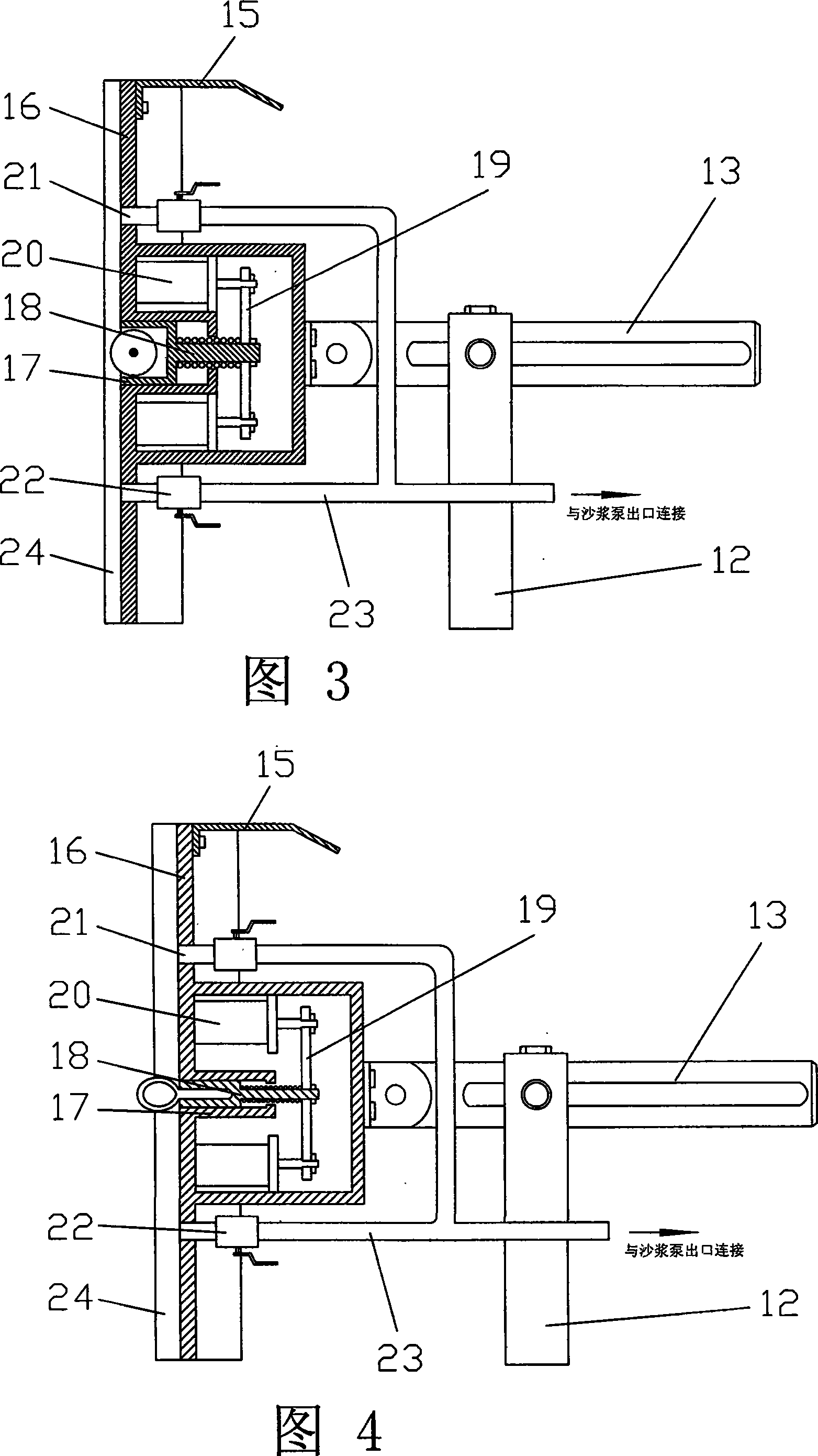
[0025] Embodiment 1: Referring to Fig. 3, Fig. 4, Fig. 9 and Fig. 10, a plastering machine, the upper part of the plastering device 14 is equipped with a baffle plate 15, the middle part is a working panel 16, and the upper middle part of the working panel 16 is provided with There is a spacer groove 17, and a spacer device 18 is installed in the spacer groove 17. The spacer device 18 is connected to the cylinder 20 on the back of the plastering device 14 through a connecting rod 19, and the middle part of the two working panels separated by the spacer device 18 is provided with an outlet. A slurry port 21, the slurry outlet 21 communicates with the valve 22 on the back of the plastering device 14, and communicates with the pipeline 23 and the ash supply system through the valve 22, and the vertical two sides of the working panel 16 of the plastering device 14 are equipped with sealing devices twenty four. In practical application, according to the actual situation of the wall...

Embodiment 2

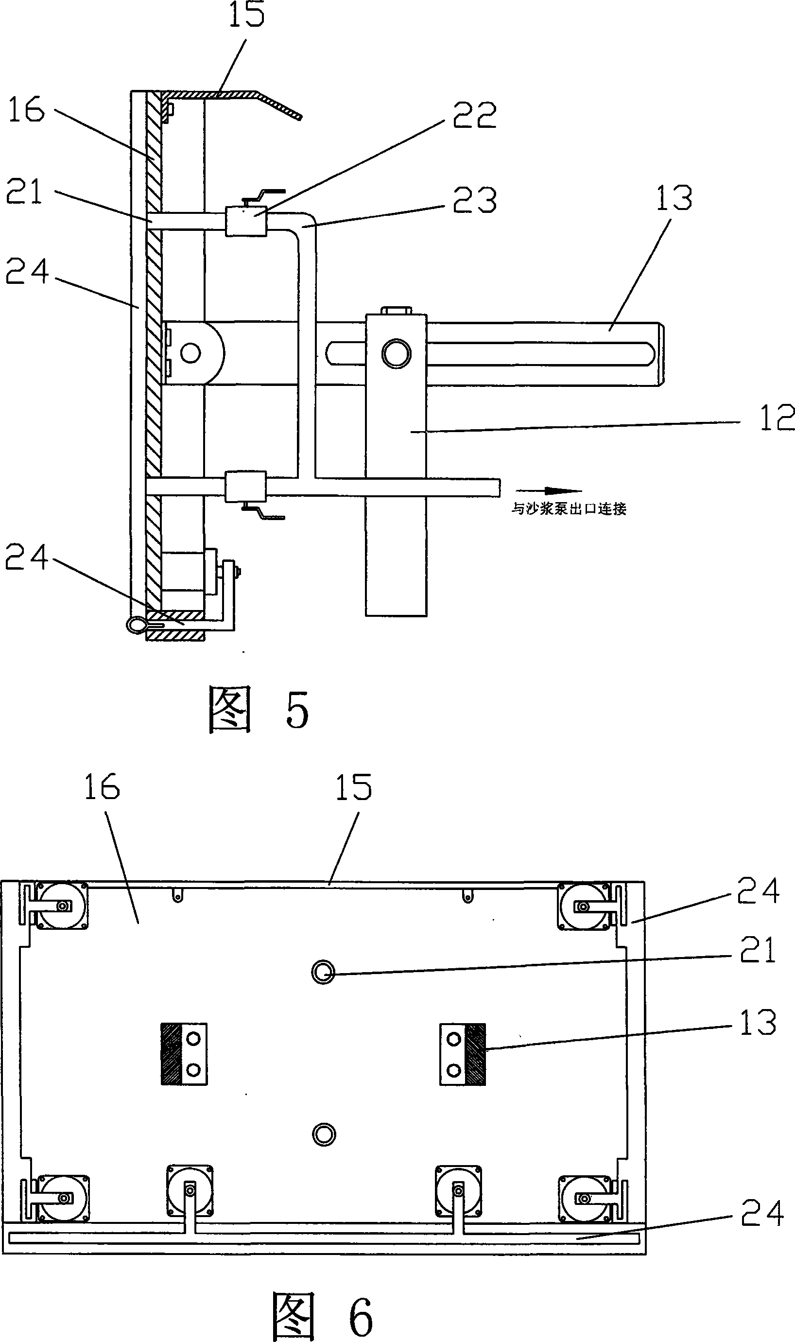
[0026] Embodiment 2: Referring to Fig. 5 and Fig. 6, a kind of plastering machine, the upper part of described plastering device 14 is equipped with baffle plate 15, and the working panel 16 of this plastering device 14 is a single plane, on the vertical plane of working panel 16 Sealing devices 24 are installed on both sides and the bottom, and a slurry outlet 21 is provided in the middle of the working panel 16. The slurry outlet 21 communicates with the valve 22 on the back of the plastering device 14, and through the valve 22 and the pipeline 23, it is connected to the ash supply system. In the same way, if the surface of the wall is relatively flat and the area is large, the plastering device 14 of this structure can be selected, and the efficiency can be effectively improved.

Embodiment 3

[0027] Embodiment 3: Referring to FIG. 7, a plastering machine, the working panel 16 of the plastering device 14 is an outer right-angle working panel 25 structure, and sealing devices 24 are installed on the two outer sides of the outer right angle of the plastering device 14, and the outer right-angle The two working panels 25 are provided with a slurry outlet 21, the slurry outlet 21 communicates with the valve 22 on the back of the plastering device 14, and communicates with the pipeline 23 and the ash supply system through the valve 22; The plastering device 14 can effectively plaster the inner corner wall.


PUM


Abstract

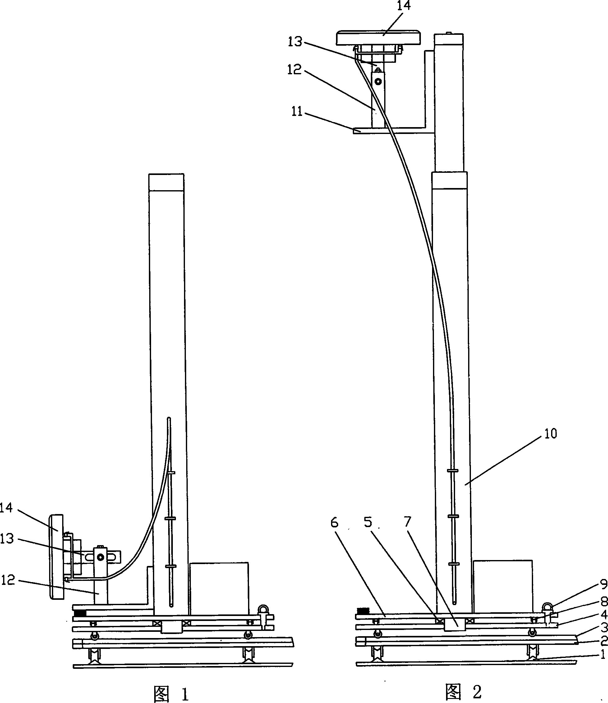
The invention relates to a pasting machine, comprising a running mechanism, an elevating mechanism, a plastering device and a paste supply system; the running mechanism comprises a longitudinal rail and a longitudinal rail trolley, a transverse rail is arranged on the longitudinal rail trolley and a transverse rail trolley is arranged on the transverse rail, an axle bed is arranged at the middle of the transverse rail trolley and the axle bed is connected with the middle of a worktable by a coupling; a bearing wheel is arranged at the bottom edge of the worktable, and a location cross pin is arranged between the worktable and the rail trolley, the elevating mechanism is arranged on the worktable and the elevating mechanism comprises an elevating support and an elevating worktable; the elevating worktable is arranged in a slideway at the inner side of the elevating support and is connected with a winch of a windlass by a rope or is connected with a hydraulic lifting device by articulation; the plastering device is arranged on the elevating worktable and a slideway is arranged in a joint rocker of the plastering device and is connected with the elevating worktable by a coupling and a support. The invention is suitable for the plastering of various walls.

Description

【Technical field】 [0001] The invention relates to a construction machine, in particular to a wall plastering machine which can adapt to various wall plastering. 【Background technique】 [0002] In the field of construction, wall plastering is a high technical level and tedious physical work. Using manual methods to plaster walls has a long construction period and low efficiency. With the progress of the times, it is an inevitable trend for mechanical plastering to replace manual plastering. When the existing plastering machine is plastering the wall, the working range is small, and the wall cannot be fully plastered. As disclosed in the Chinese Patent Gazette, the patent No. 93219089.8 is called "vibration plastering machine" , when plastering the wall, it can only be used for a large area of ​​the wall, and it is not suitable for plastering the internal corners, external corners, ceilings, window sills, stairs, columns and other parts of the wall, and the plastering of the ...

Claims


Application Information

Patent Timeline
Patent Type & Authority Applications(China)
IPC IPC(8): E04F21/08
Inventor 邓国飞
Owner 邓国飞
Learn More