Radio relay communication method, radio base station, and radio relay station in radio communication system

A radio relay, radio base station technology, applied in radio transmission systems, radio relay systems, wireless communications, etc., can solve problems such as reduced throughput, message and data reception errors, and reduced radio resource utilization, and achieve improved success. The effect of receiving rate, improving utilization rate, and ensuring communication quality

Inactive Publication Date: 2008-02-20
FUJITSU LTD
View PDF0 Cites 36 Cited by
  • Summary
  • Abstract
  • Description
  • Claims
  • Application Information

AI Technical Summary

Problems solved by technology

In such a case, the planned reception timing at the MS 300 assumed by the BS 100 and the planned reception timing calculated by the MS 300 based on an instruction from the BS 100 represent a point in time that is greatly different, resulting in reception errors of messages and data
[0017] If such a recepti

Method used


Image

  • Radio relay communication method, radio base station, and radio relay station in radio communication system
  • Radio relay communication method, radio base station, and radio relay station in radio communication system
  • Radio relay communication method, radio base station, and radio relay station in radio communication system

Examples


Embodiment Construction

[0075] Embodiments of the present invention will be described in detail below with reference to the accompanying drawings. It is needless to say that the present invention is not limited to this embodiment, and various modifications can be implemented without departing from the spirit of the present invention.

[0076] [A] Description of Examples

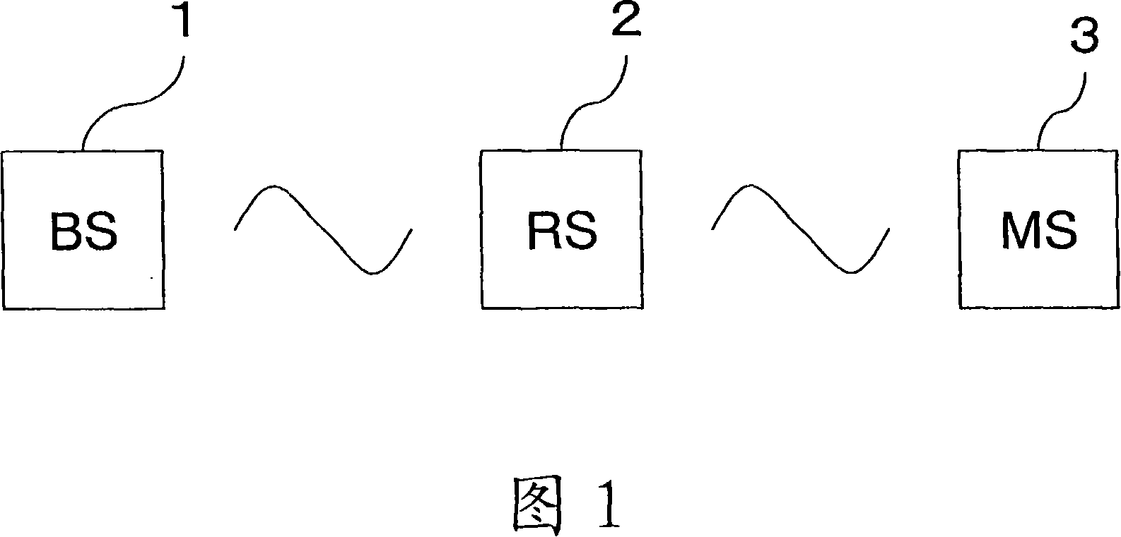
[0077] 1 is a block diagram showing the configuration of a radio communication system according to an embodiment of the present invention, the radio communication system shown in FIG. 1 includes a radio base station (BS) 1, a mobile station (MS) equipped with a radio communication function as a wireless terminal 3 (such as a mobile phone and a laptop PC), and a radio relay station (RS) 2 disposed between the BS 1 and the MS 3. In this embodiment, RS 2 corresponds to a mobile station for BS 1, serves as a radio base station for MS 3, temporarily receives radio (RF) signals transmitted by BS 1 or MS 3, and performs necessary After p...


PUM


Abstract

Correct reception of messages and data by a mobile station or radio base station is enabled in a planned timing by adjusting a receiving or transmit timing in consideration of a time (an occurrence of a time lag) required for relay processing in a radio relay station within a radio communication system. For that purpose, time lag information related to a relay delay due to relay processing in theradio relay station is set to the radio base, the receiving timing of the mobile station is determined based on the time lag information, and the transmit timing of the radio base station 1 or the receiving timing of the mobile station is controlled according to the determined receiving timing.

Description

technical field [0001] The invention relates to a radio relay communication method, a radio base station and a radio relay station in a radio communication system. Background technique [0002] In recent years, as a radio communication technology, a technology called WiMAX (Worldwide Interoperability for Microwave Access) has attracted attention. WiMAX was developed as a technology for constructing a wireless MAN by enabling communication carriers and user households to be connected by radio instead of telephone lines or optical fiber lines, and enabling MAN (Metropolitan Area Network) of LAN (Local Area Network) interconnected WAN is wireless, and WiMAX can cover an area with a radius of about 50 km at a transmission speed of up to 70 Mbps using one radio base station. [0003] Currently, for example, IEEE has standardized IEEE Standard 802.16-2004 (2004-10-01) and IEEE Standard 802.16-2004 / Cor1 / D5 (2005-09-12) as WiMAX for fixed e / D12 (2005-10-14) is standardized as WiMA...

Claims


Application Information

Patent Timeline
IPC IPC(8): H04B7/14H04Q7/30H04L12/28H04W92/10
CPCH04B7/155H04W56/0045
Inventor 中津川惠一
Owner FUJITSU LTD
Why Eureka
Try Eureka