Cast-in-place shaping construction method and shaping equipment

A technology of forming equipment and construction methods, which is applied to the preparation of building components on site, construction, building components, etc., can solve the problems of single formwork structure and material, difficult to meet infrastructure construction, rigid implementation methods, etc., and achieve construction Convenience, sound insulation and shock resistance, smooth surface

Inactive Publication Date: 2008-02-27
于永久
View PDF0 Cites 8 Cited by
  • Summary
  • Abstract
  • Description
  • Claims
  • Application Information

AI Technical Summary

Problems solved by technology

[0002] Traditional on-site pouring and molding equipment mostly assembles the forming template at one time, and pours it in place at one time. The forming template structure and material are single, the precision is poor, and the implementation method is rigid, which is difficult to meet the growing requirements of infrastructure construction.

Method used


Image

  • Cast-in-place shaping construction method and shaping equipment
  • Cast-in-place shaping construction method and shaping equipment
  • Cast-in-place shaping construction method and shaping equipment

Examples


Embodiment 1

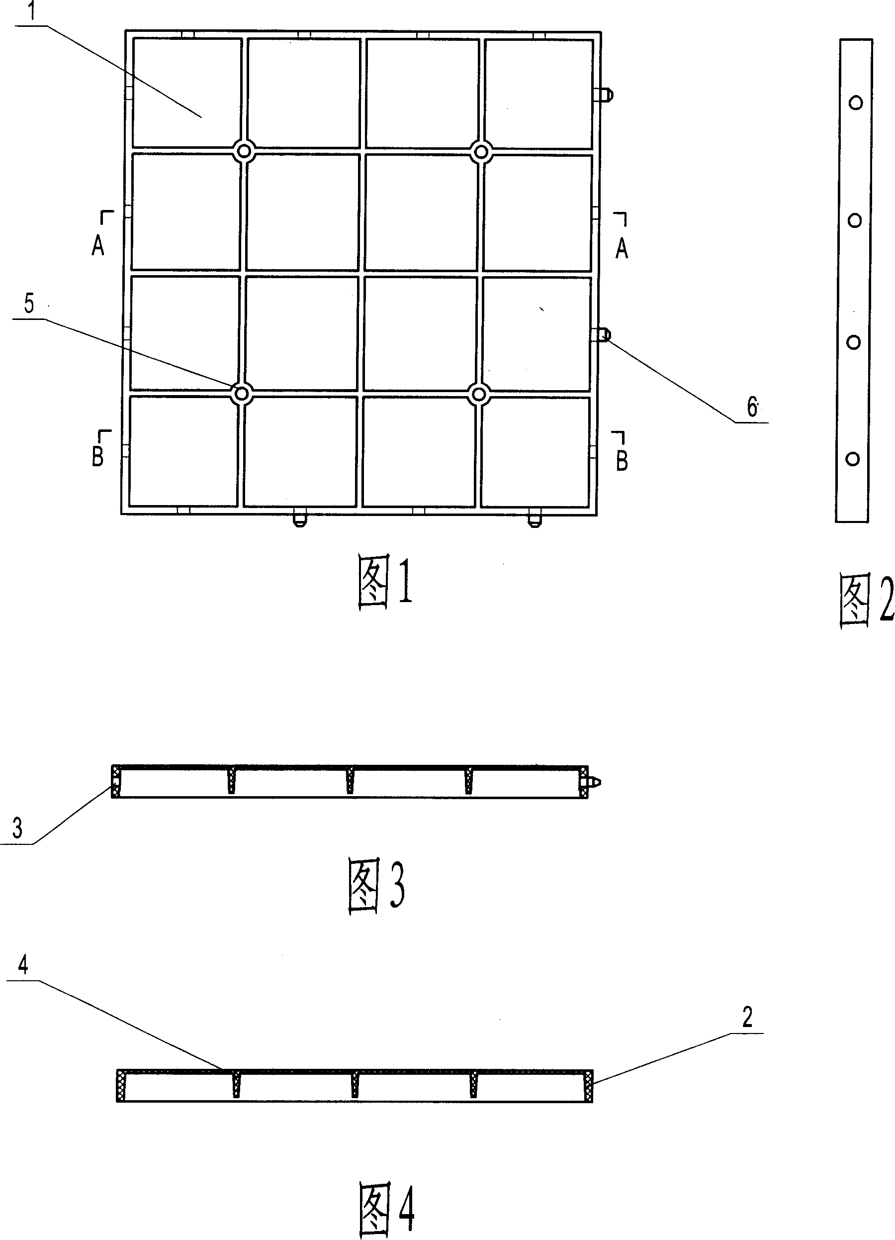
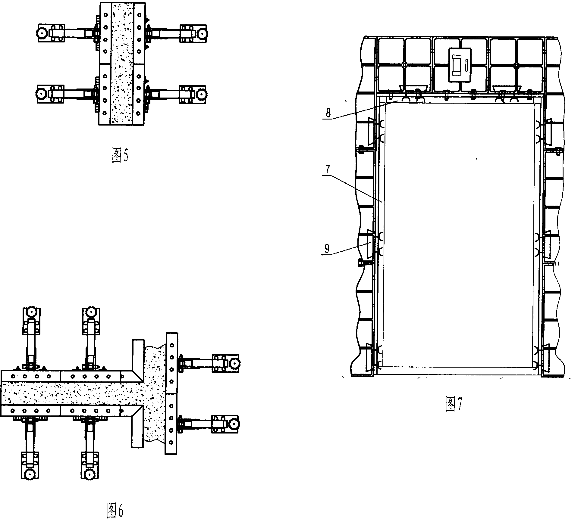
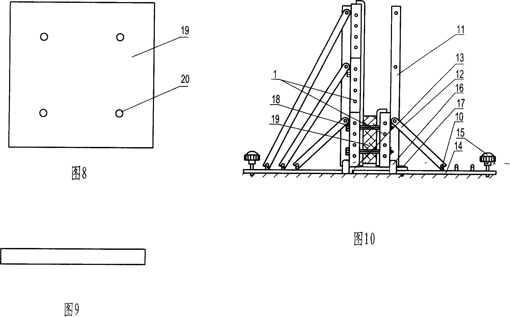
[0038] In the construction method of pouring-in-place molding for construction, first form the formwork into a whole formwork, place it on the wall to be formed, and adjust the whole formwork to the use requirements by adjusting the adjustment mechanism, and then continue to assemble the formwork group into another whole The template, the height of which is one template height, as shown in Figure 11, put the forming inner core between the two assembled overall templates, and then connect the two forming templates and the forming inner core through long positioning pins, and the forming inner core The positioning piece should be inserted into the hole first, and its length is equal to the thickness of the wall. The positioning of the forming inner core in the left and right direction is limited by the limit rubber strip 22. The locating pin 23 and the hole 3 on the forming template cooperate to realize positioning.

[0039] Inject the adjusted slurry between the two integral fo...

Embodiment 2

[0041] In-situ pouring molding construction method for construction, the forming formwork and forming inner core are assembled into a formwork height and the use status is adjusted as shown in Figure 14, and then the injection vibration process is completed into the mold cavity, and the second layer of wall is made in the same way After the second layer of wall is completed, the first layer of wall has reached the state of gelling and demoulding, and the forming template is removed to make the third layer of wall. Repeat the above-mentioned production process to complete the cast-in-place wall. If the demolition state is not reached, idle formwork can be used to make the remaining wall, as shown in Figure 15.

Embodiment 3

[0043] In the construction method of on-site pouring and forming for construction, the formwork is formed into two integral formworks, and the preformed wall panels are clamped and cast in any of the above-mentioned implementation methods. The preformed wall panels can be placed vertically as shown in Figure 16, or It can be placed horizontally as shown in Fig. 17, wherein the preformed wallboard is a pouring area at a certain distance.


PUM


Abstract

The present invention is in-situ pouring and forming construction process and apparatus for building. The in-situ pouring and forming construction process includes the following steps: assembling forming formwork parts to form the first forming formwork, setting the first forming formwork to where the wall is formed and regulating, setting the second forming formwork, setting one forming core between two forming formworks, jointing two forming formworks and the forming core with locating pins, pouring slime into the forming formworks to form, assembling further the other forming formworks, repeating the said steps in the second height, etc until completing the in-situ pouring and forming construction. The present invention is suitable for forming water kinds of building wall.

Description

Technical field: [0001] The invention relates to a building construction method, in particular to a construction method and molding equipment for on-site pouring and molding for buildings. Background technique: [0002] Traditional on-site pouring and molding equipment mostly assembles the forming template at one time, and pours it in place at one time. The forming template structure and material are single, the precision is poor, and the implementation method is rigid. It is difficult to meet the growing requirements of infrastructure construction. Invention content: [0003] The purpose of the present invention is to provide a convenient construction, leveling-free, high-precision construction site cast-in-place molding construction method and molding equipment. [0004] Above-mentioned purpose realizes by following technical scheme: [0005] An on-site forming construction method for buildings. Firstly, a group of forming templates is taken and connected to form a whol...

Claims


Application Information

Patent Timeline
Patent Type & Authority Applications(China)
IPC IPC(8): E04B2/84E04G11/08E04G17/00
Inventor 于永久
Owner 于永久
Why Eureka
Try Eureka