
Integrating controller of CD driver optical reading head and holding tray motor and control method thereof

A technology of optical reading head and controller, which is applied in the direction of optical recording/reproduction, instrument, head configuration/installation, etc., so as to avoid mutual interference and improve work efficiency

Inactive Publication Date: 2008-02-27
BENQ CORP
View PDF0 Cites 3 Cited by
  • Summary
  • Abstract
  • Description
  • Claims
  • Application Information

AI Technical Summary

Problems solved by technology

[0014] The above is the method of controlling the tilt actuator and the tray motor of the optical pickup actuator in the prior art. The disadvantage is that two controllers are required to control the tilt actuator and the tray motor on the optical pickup actuator respectively. , thus requiring many hardware

Method used


Image

  • Integrating controller of CD driver optical reading head and holding tray motor and control method thereof
  • Integrating controller of CD driver optical reading head and holding tray motor and control method thereof
  • Integrating controller of CD driver optical reading head and holding tray motor and control method thereof

Examples


no. 1 example

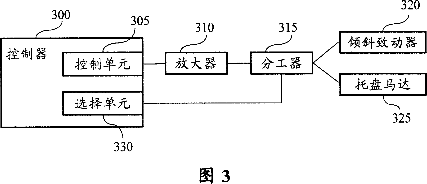
[0028] Please refer to FIG. 3 , which is a block diagram of a first embodiment of the present invention. The first embodiment of the present invention includes a controller 300 , an amplifier 310 , a divider 315 , a tilt actuator 320 , and a tray motor 325 . The controller 300 includes a control unit 305 and a selection unit 330 . The controller 300 transmits the control signal to the control unit 305, and the control unit 305 transmits the control signal to the amplifier 310 according to the transmitted control signal. The selection signal at 330 outputs a control signal to the tilt actuator 320 or the tray motor 325 to make corresponding actions.

[0029] Please refer to FIG. 4 , and refer to FIG. 3 . Fig. 4 is a flowchart of the first embodiment of the present invention. The instructions are as follows:

[0030] Step 400: start;

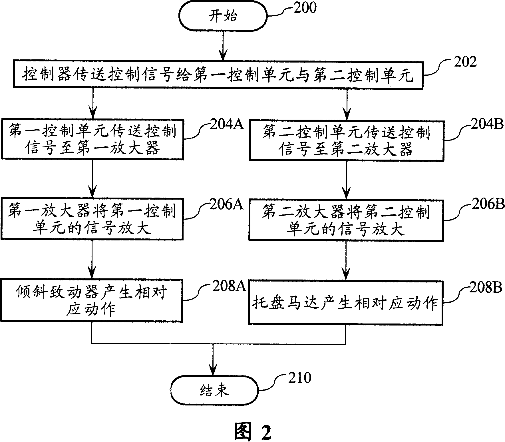
[0031] Step 402: the controller 300 sends a control signal to the control unit 305 and the selection unit 330;

[0032] Step 404: the contr...


PUM


Abstract

This invention discloses a kind of control system which control the declivity angle actuator and salver motor of the CD driver, includes: the controller, it includes the control cell which produces the control signal and the choice cell which output the choice signal; the signal amplifier, coupled links with the control cell to amplify the control signal transmitted by the control cell; the divided device, whose input terminal links with the signal amplifier, the control terminal links with the choice cell; the declivity angle actuator, links with the first output terminal of the divided device to control the declivity angle of the optics read head; and the salver motor, links with the second output terminal of the divided device.

Description

technical field [0001] The invention relates to a system for controlling an optical drive, especially a control system for integrated control of an optical pickup head and a tray motor. Background technique [0002] The control of the optical drive can generally be divided into four parts: (1) spindle motor control (spindle motor control); (2) optical pickup head position and speed control (sledge motor control); (3) optical pickup head actuator control (separate (focus, radial and tilt actuators); and (4) tray motor control. Generally speaking, the tilt control of the optical read head actuator is closer to the signal of the tray control, so the control of this part of the optical drive is often integrated into the same main controller, and then different auxiliary controllers are used to control the optical read separately. Head actuator and tray motor. [0003] Please refer to Figure 1. FIG. 1 is a block diagram of controlling the tilting motion of the pickup head and ...

Claims


Application Information

Patent Timeline
IPC IPC(8): G11B7/09G11B7/095G11B17/053G11B19/02
Inventor 林松尧
Owner BENQ CORP
Features
  • Generate Ideas
  • Intellectual Property
  • Life Sciences
  • Materials
  • Tech Scout
  • Unparalleled Data Quality
  • Higher Quality Content
  • 60% Fewer Hallucinations
Learn More