Feeder unit of the centrifugal discharging type centrifugal machine

A technology for unloading centrifuges and feeding devices, which is applied to centrifuges and centrifuges with rotating drums, etc. It can solve problems such as discontinuous working process, centrifuge vibration, and prone to mechanical failures, so as to reduce mechanical Failure, smooth operation effect

Active Publication Date: 2008-03-12
JIANGSU PEONY CENTRIFUGE MFG
View PDF0 Cites 4 Cited by
  • Summary
  • Abstract
  • Description
  • Claims
  • Application Information

AI Technical Summary

Problems solved by technology

In this way, whether the suspension can be evenly distributed at the small end of the drum becomes the key to the separation and discharge process. If the suspension cannot be evenly distributed along the circumference of the drum body at the small end of the drum, it will inevitably make the entire working process discontinuous and more serious. The most important thing is: if the suspension and filter residue are not evenly distributed on the circumference of the drum body, the centrifuge under high-speed operation will vibrate violently, which is very prone to mechanical failure and endanger personal safety
In fact, since the concentration, input volume and flow rate of the suspension in most processes cannot be stable and consistent, and there may be errors in the assembly of the distributor, it is difficult for this feeding device to make the suspension small along the drum. Evenly distributed around the circumference of the drum at the end

Method used


Image

  • Feeder unit of the centrifugal discharging type centrifugal machine

Examples


Embodiment Construction

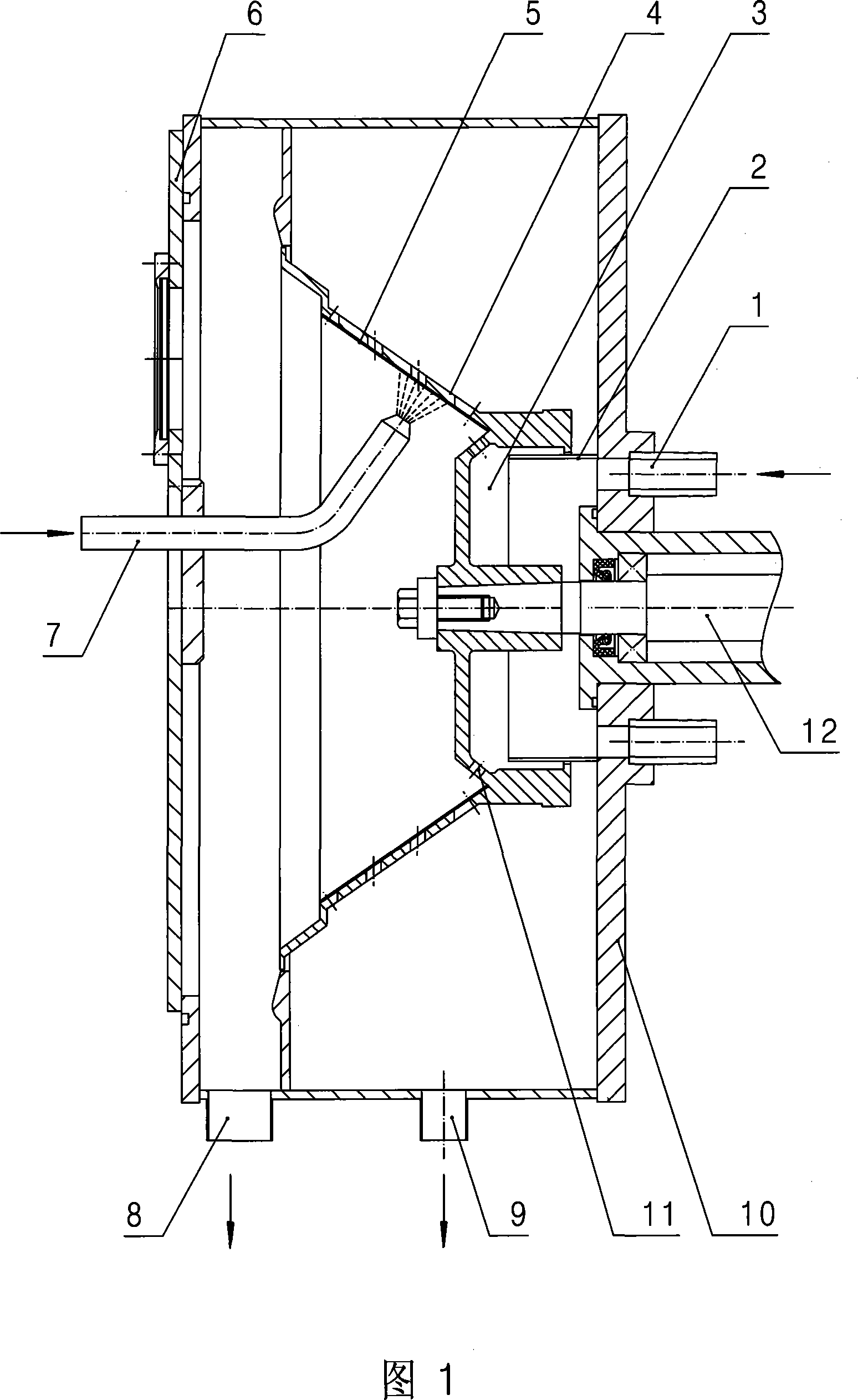
[0009] Specific embodiments of the present invention will be described in detail below in conjunction with the accompanying drawings.

[0010] As shown in Figure 1, the feeding device in the centrifugal discharge centrifuge of the present invention includes: a casing 10, a main shaft 12 driven by a main shaft motor is movably arranged in the casing 10, and a drum is arranged on the main shaft 12 4. The outer side of the bottom of the drum is sunken inward to form a silo 3, the bottom of the silo 3 communicates with several evenly arranged feed holes 11 arranged on the same circumference at the bottom of the drum 4; the inner wall of the casing 10 A hopper 2 matched with the silo 3 is provided, and the hopper 2 communicates with several feed pipes 1 pierced in the casing 10 . In this embodiment, the several feed pipes 1 are evenly passed through the casing 10 with the main shaft 12 as the center.

[0011] The working process of the centrifuge equipped with the present inventio...


PUM


Abstract

The present invention discloses a feeding device in an unloading centrifuge, which can make a suspension distribute evenly along a circumference of a small end of a rotary drum. The present invention comprises a machine shell. A rotating principal axis is arranged in the machine shell and is equipped with the rotary drum. The external side of the bottom of the drum is concave inwards to form a material silo. The bottom of the material silo communicates with a plurality of material holes evenly arranged on the same circumference at the bottom of the drum. The interior wall of the machine shell is equipped with a material discharge hopper cooperating with the material silo, and the material discharge hopper communicates with a plurality of feed pipes going through the machine shell. The feeding device of the present invention can make the centrifuge operate smoothly in the working course, so as to ensure the normal operation of filtering, spinning, unloading and other courses of the centrifuge and reduce the mechanical problems greatly.

Description

technical field [0001] The invention relates to a centrifugal discharge centrifuge, in particular to a feeding device in the centrifugal discharge centrifuge. Background technique [0002] Centrifugal discharge centrifuge is an automatic continuous discharge centrifuge without mechanical discharge device. The drum is conical, and the filter residue is in the conical drum, relying on the centrifugal force it receives to overcome the friction between it and the screen, so that the filter residue moves along the surface of the screen to the big end of the drum, and finally it is discharged from the drum by itself. Complete separation and unloading while moving. Since this kind of centrifuge automatically and continuously completes the processes of feeding, separating, drying and unloading at full speed, it has the advantages of simple structure, high efficiency, large processing capacity, low operation and maintenance costs, etc. It is used in chemical, food, mining, etc. ind...

Claims


Application Information

Patent Timeline
Patent Type & Authority Applications(China)
IPC IPC(8): B04B3/00B04B11/02B04B11/06
Inventor 顾坤一张海张威陈伟陈亚东
Owner JIANGSU PEONY CENTRIFUGE MFG
Why Eureka
Try Eureka