Transformer device structure and manufacture method

A transformer and magnetic core technology, applied in the field of transformer structure and manufacturing method, can solve the problems of difficult control, brittleness of the dispensing 15, uneven bottom surface, etc., to achieve the effect of easy operation and control, and improved reliability and stability.

Active Publication Date: 2008-03-12
DELTA ELECTRONICS INC
View PDF0 Cites 3 Cited by
  • Summary
  • Abstract
  • Description
  • Claims
  • Application Information

AI Technical Summary

Problems solved by technology

[0005] However, since the dispensing glue 15 is provided on a small portion of the bottom surface of the second concave portion 1323 of the second magnetic core portion 132, the bottom surface of the second concave portion 1323 of the second magnetic core portion 132 will become uneven.
In addition, the area of ​​the second concave portion 1323 of the second magnetic core portion 132 is relatively small, so that the glue dispensing operation is not easy to carry out and control, and the dispensing amount often occurs unevenly, causing the circuit board 11 to be unable to be firmly fixed.
In addition, when the circuit board 11 is installed and fixed on the bottom surface of the second recess 1323 of the second magnetic core part 132 first, since the circuit board 11 cannot be smoothly attached and fixed to the second magnetic core part 132, the circuit board 11 is relatively opposite to the second magnetic core part 132. The bottom surface of the second concave part 1323 of the second magnetic core part 132 presents an inclined shape, which causes the flatness of the plurality of pins 12 of the transformer 1 to be poor and difficult to control, and then makes the transformer 1 unable to use surface mount technology due to poor soldering of the pins 12 Firmly fixed on the system circuit board, even affecting the stability and reliability of the product
In addition, if the traditional transformer 1 is installed on the circuit board of the system and goes through the process of tin furnace, the dispensing glue 15 will be easily brittle due to the material, which will cause the circuit board 11 of the transformer 1 and The magnetic core group 13 cannot be firmly fixed
What's more, since there is still a gap between the circuit board 11 and the bottom surface of the second recess 1323 of the second magnetic core part 132 and / or the bottom surface of the first recess 1313 of the first magnetic core part 131, and the air existing in the gap As a poor heat conduction medium, the traditional transformer 1 cannot properly solve the problem of heat dissipation for power supply devices and power conversion devices with increasing power

Method used


Image

  • Transformer device structure and manufacture method
  • Transformer device structure and manufacture method
  • Transformer device structure and manufacture method

Examples


Embodiment Construction

[0067] Some typical embodiments embodying the features and advantages of the present invention will be described in detail in the description in the following paragraphs. It should be understood that the present invention can have various changes in different embodiments without departing from the scope of the present invention, and the description and drawings therein are used as illustrations in nature rather than limiting the present invention .

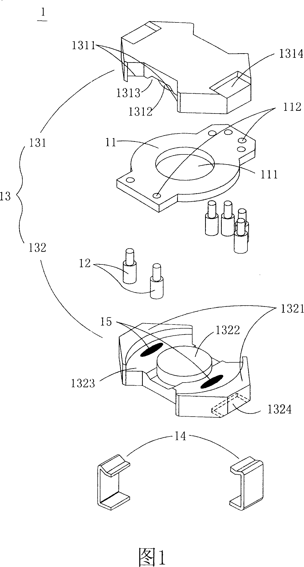
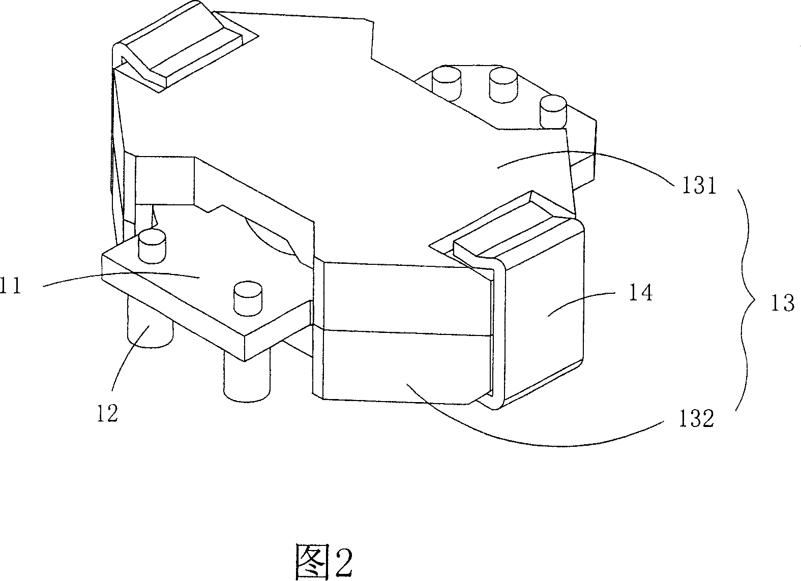
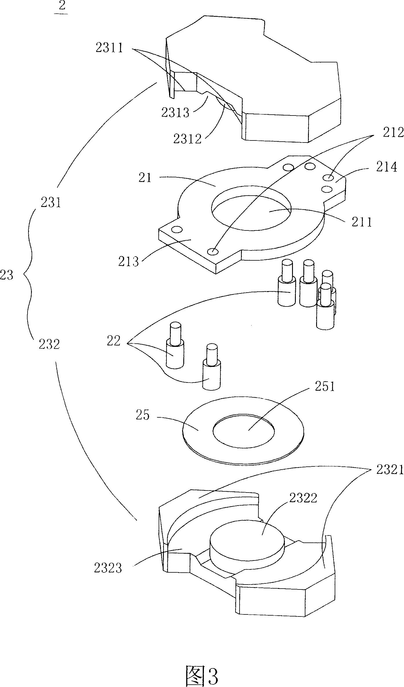
[0068] Please refer to FIG. 3 , which is a schematic structural diagram of a transformer in a preferred embodiment of the present invention. As shown in FIG. 3, the transformer 2 of the present invention can be, for example, a surface mount device (Surface Mount Device, SMD) type transformer, and its structure includes a circuit board 21, a plurality of pins 22, a magnetic core group 23 and at least one interface layer 25, wherein the circuit board 21 can be, for example, a multi-layer structure and has a winding circuit to form ...


PUM


Abstract

The invention is a transformer structure and its manufacturing method, which at least comprises a magnetic core set with the first magnetic core unit and second magnetic core unit, a circuit wafer mounted between the first magnetic core unit and second magnetic core unit with winding circuit to form primary and at least one secondary winding, a plurality of pins set on the circuit wafer, and at least an interface layer equipped between the first magnetic core unit and the circuit wafer as well as / or between the second magnetic core unit and the circuit wafer. The transformer structure provided by the invention can not only fix the circuit wafer stably, but also can make the pins of the transformer possess optimized planeness through the setting of the interface layer. Besides, the invention also avoids minus effect of tin immersion when the transformer sets the contact pads linked with the system circuit wafer by surface mounting technology, and improves the reliability and stability of the products.

Description

technical field [0001] The invention relates to a transformer structure and manufacturing method. Background technique [0002] A transformer is an indispensable basic component for the operation of various electronic devices, such as power supply devices or power conversion devices. As the power supply device or power conversion device develops towards miniaturization and high power, the transformer also needs to be improved in the direction of small size and flat structure. Please refer to FIG. 1 , which is a schematic structural diagram of a traditional transformer. As shown in FIG. 1 , a conventional transformer 1 includes a circuit board 11, a plurality of pins 12, a magnetic core group 13 and a fixing element 14, wherein the circuit board 11 can be, for example, a multi-layer structure and has winding lines to form primary windings and Secondary winding (not shown). The circuit board 11 also has a through hole 111 and a plurality of guide holes 112, wherein the thro...

Claims


Application Information

Patent Timeline
IPC IPC(8): H01F27/40H01F27/24H01F41/00
Inventor 郑瑞珠林财申许素琼
Owner DELTA ELECTRONICS INC
Why Eureka
Try Eureka