
Air spinning machine with monitoring of the spinning process by means of sensors

An open-end spinning machine and sensor technology, which is used in continuous winding spinning machines, spinning machines, open-end spinning machines, etc., can solve the problems of blocking vortex chambers, fibers not being sucked away, and air vortex interference.

Inactive Publication Date: 2008-03-12
MASCHINENFABRIK RIETER AG
View PDF0 Cites 3 Cited by
  • Summary
  • Abstract
  • Description
  • Claims
  • Application Information

AI Technical Summary

Problems solved by technology

It is possible that the unentrained fibers are not sucked away and block the vortex chamber 29, which will become a disturbance to the air vortex or the air vortex is disturbed by other influencing factors
This immediately results in the fiber not being optimally wound
Unfortunately, this negative effect of the spinning process is not often noticed, i.e. the yarn breaks but the spinning process continues in a seemingly "normal" manner, resulting in a poor quality yarn, i.e. especially yarn tenacity decreases

Method used

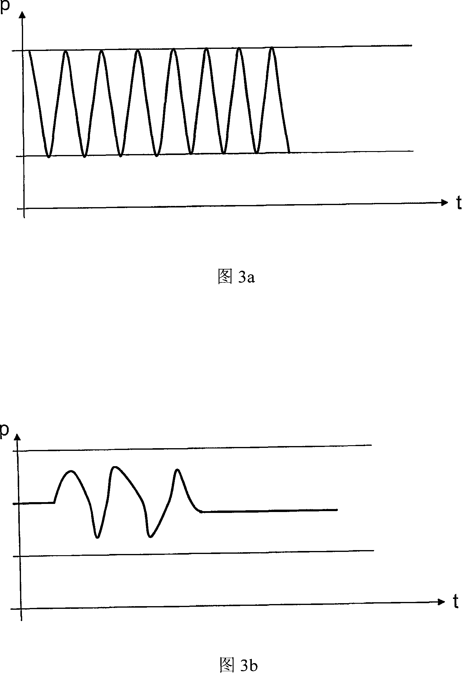

Image

  • Air spinning machine with monitoring of the spinning process by means of sensors
  • Air spinning machine with monitoring of the spinning process by means of sensors
  • Air spinning machine with monitoring of the spinning process by means of sensors

Examples


Embodiment Construction

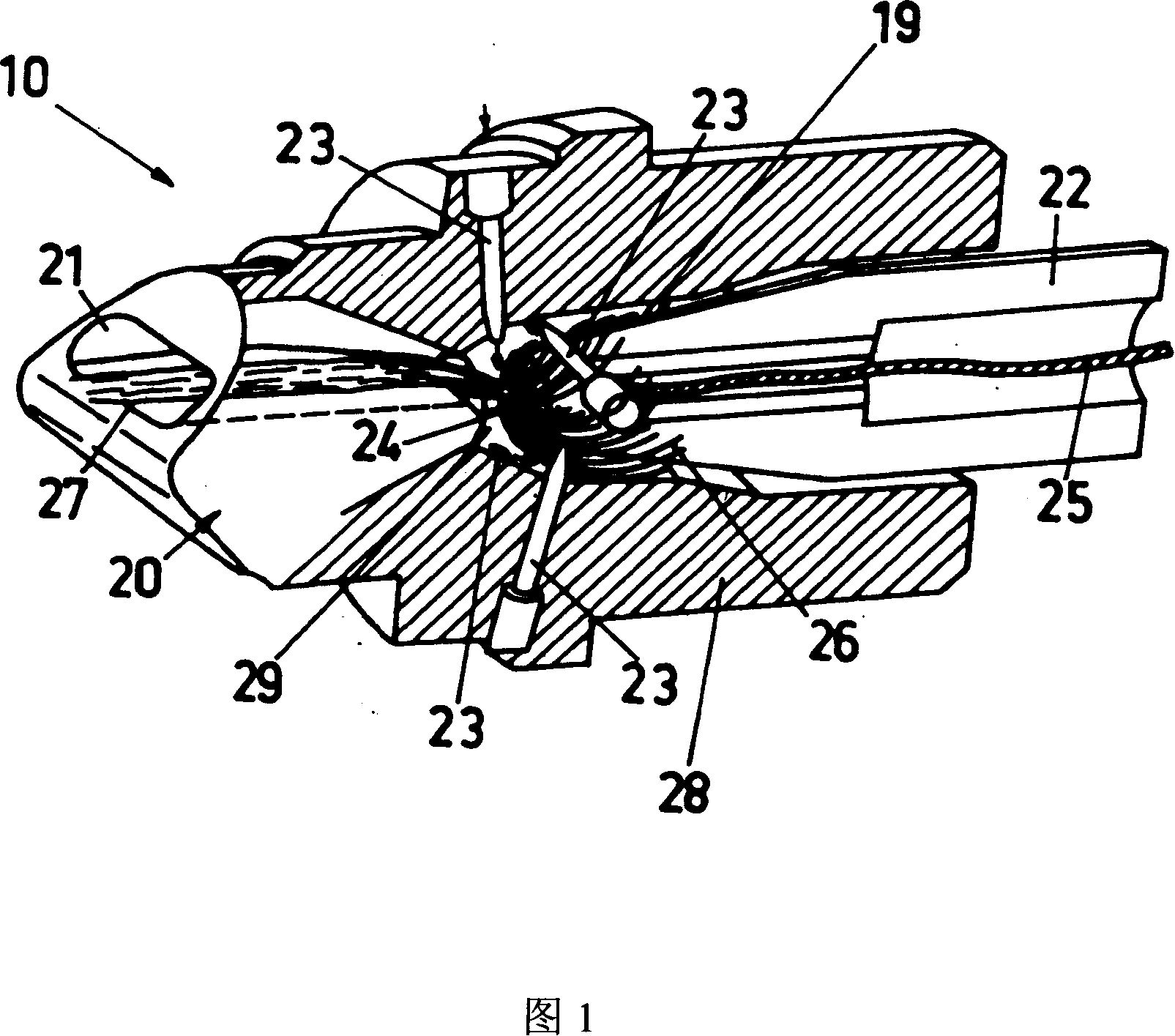
[0024] In order to explain the facts described hereinafter, FIG. 1 shows a perspective view of a spin pot 10 known per se, hereinafter referred to as spindle 10 , comprising a thread-guiding element 20 and a spindle 22 . The yarn sliver 27 is guided through the yarn guide element 20 into the swirl chamber 29 as far as the spindle hole 24 . The vortex created by the compressed air supplied by the air nozzle 23 spins the sliver 27 into a yarn 25 which is drafted through the yarn drawing channel of the spindle 22 to a winding device (not shown). Figure 1 does not show exactly the air duct 19, which is used to expel the air and release the fibres.

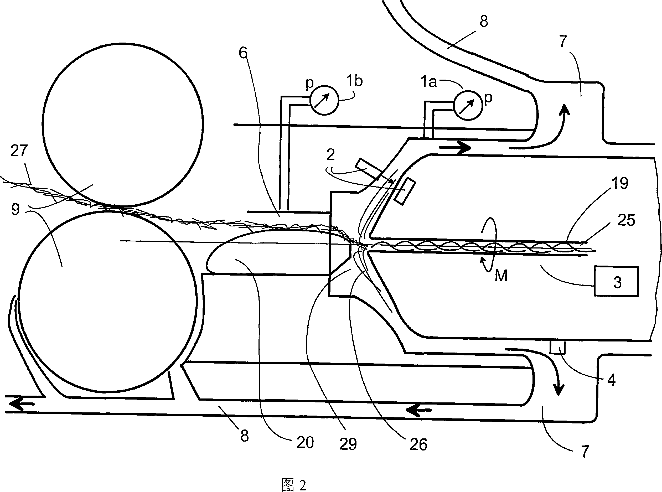
[0025] From the context of figure 1, figure 2 shows a particular arrangement of sensors at the spinning spindles in an embodiment of the spinning machine according to the invention. It should be noted here that the type and number of sensors shown can be freely combined.

[0026] As is known, during the air-jet spinning process so-ca...


PUM


Abstract

In air spinning machines the air vortex and the winding of the fibres are extremely important to the quality of the spun yarn (25). According to the invention, an air spinning machine is disclosed for the early detection of quality losses whereby at least one sensor (1a, 1b, 2, 3, 4) is provided per spinning post which records a physical parameter of the air vortex and / or a winding parameter. The recorded parameters are analysed in a monitoring unit and hence permit a control of the spinning process.

Description

technical field [0001] The invention relates to an air spinning machine with a plurality of spinning posts according to the preamble of claim 1 . Background technique [0002] An air spinning machine consists of several spinning spindles. In each spinning spindle the yarn is spun from a supplied longitudinal fiber structure. Here, the longitudinal fiber structure is first refined, ie the number of fibers per unit length is reduced by drawing. Thus, the refined sliver is spun into yarn by twisting. This twisting process is accomplished by means of air vortices. [0003] The essential components of a spinning spindle according to the prior art are shown in perspective view 1 . The negative pressure generated by the air vortex in the vortex chamber 29 sucks the parallel oriented sliver 27 through the thread guide element 20 . Consolidation, ie the spinning process of the yarn 25, is achieved by means of air vortices. The free fiber ends 26 of the sliver 27 are picked up b...

Claims


Application Information

Patent Timeline
IPC IPC(8): D01H4/02D01H1/115D01H13/20
CPCD01H13/20D01H1/115D01H4/02
Inventor 福尔克尔·耶勒菲利普·高席格尔德·施塔勒克
Owner MASCHINENFABRIK RIETER AG
Learn More