Gas sensor and method for the production thereof and uses

A sensor and gas technology, applied in gas sensors and their manufacturing and application fields, can solve problems such as gas sensor failure

Inactive Publication Date: 2010-12-15
ROBERT BOSCH GMBH
View PDF6 Cites 0 Cited by
  • Summary
  • Abstract
  • Description
  • Claims
  • Application Information

AI Technical Summary

Problems solved by technology

Since these through-holes have relatively large tolerances due to machining, such a sea

Method used


Image

  • Gas sensor and method for the production thereof and uses
  • Gas sensor and method for the production thereof and uses
  • Gas sensor and method for the production thereof and uses

Examples


Embodiment Construction

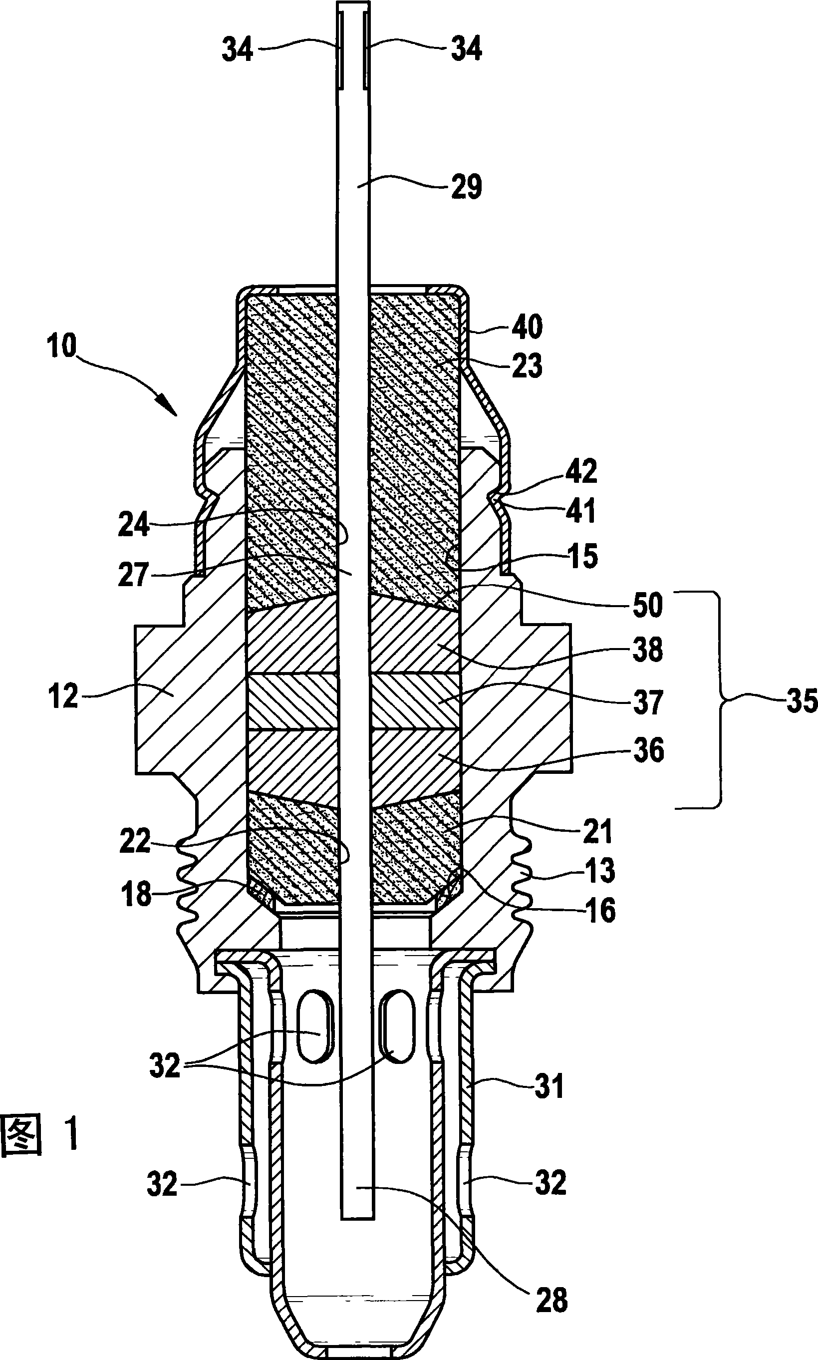
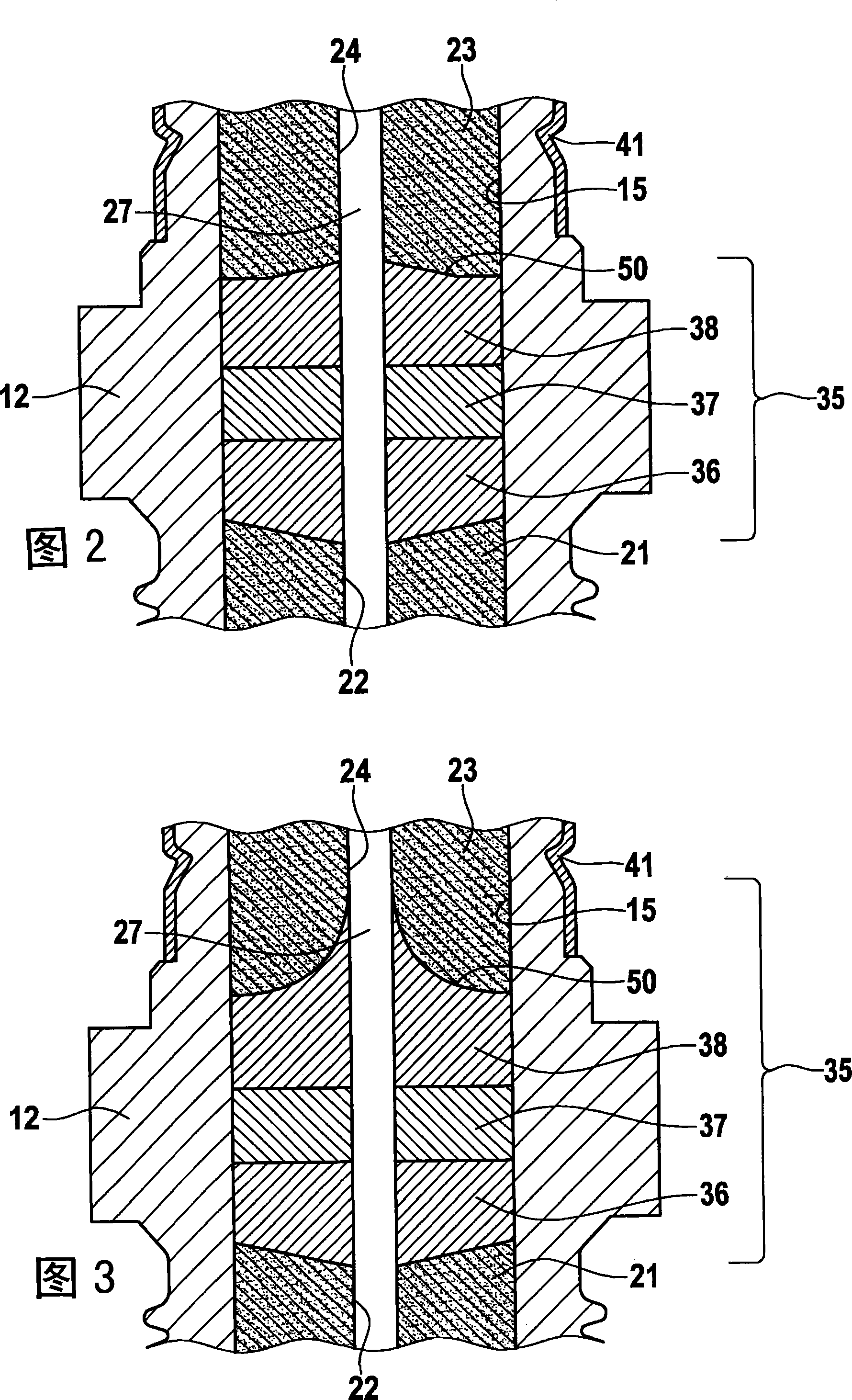
[0027] figure 1 shows the schematic structure of a sensor for determining a gas in a gas mixture. The sensor 10 is, for example, an electrochemical oxygen sensor, which includes a metal housing 12, which has a screw thread 13 as a fixing mechanism for being installed in a not shown gas pipe to be measured. The gas line is configured, for example, as an exhaust gas conduction system. The housing 12 has a longitudinal bore 15 with a shoulder-shaped annular surface 16 . For example, a metallic sealing ring 18 rests on the shoulder-shaped annular surface 16 , against which a measured gas-side ceramic molding 21 rests. The measured-gas-side ceramic molding 21 has a centrally arranged, measured-gas-side through-opening 22 extending in the direction of the longitudinal bore 15 . A connection-side ceramic molding 23 is also provided in the longitudinal bore 15 at a distance from the measured gas-side ceramic molding 21 . The connection-side ceramic molding 23 also has a centrally ...


PUM


Abstract

The invention relates to a gas sensor for determining gases in gas mixtures comprising a sensor element (27) which is fixed in a sensor housing (12) and surrounded with a seal joint (35) between a connecting area (29) and an area (28) oriented towards the gas mixture, whereby said seal joint (35) is delimited in the sensor longitudinal direction by a shaped body (21, 23), respectively, provided with a passage (22, 24) for the sensor element (27). In such a manner, the limiting surface oriented to the seal joint (35) of at least one shaped body (21, 23) is provided with a practically conical or truncated recess (50) and the conical surface of the cone or truncated cone and the base surface thereof form an angle ranging from 1 to 38 DEG .

Description

technical field [0001] The invention relates to a sensor for determining a gas in a gas mixture, a method for its manufacture and its use. Background technique [0002] Gas sensors for determining the gases in the exhaust gas of internal combustion engines are usually based on a ceramic sensor element which is fastened in the metal housing of the sensor and is opposed to the combustion chamber or the exhaust tract by means of a suitable seal. Corrosive gases that occur are sealed. [0003] An electrochemical measuring sensor is known, for example, from DE 1000 95 97 A1, in which a small plate-shaped ceramic sensor element is held in a metal housing. In order to seal the sensor element, the measuring sensor has a sealing device consisting of two sealing elements comprising a mixture of talc powder and boron nitride powder, wherein another sealing element is arranged between the two sealing elements. Sealing elements made of boron nitride. The seal is bounded within the hou...

Claims


Application Information

Patent Timeline
IPC IPC(8): G01N27/407
CPCG01N27/4078G01N27/407
Inventor S·内斯H·希普L·迪尔A·沙克
Owner ROBERT BOSCH GMBH
Why Eureka
Try Eureka