Tread splicing apparatus

An automatic jointing and treading technology, which is applied to tires, other household appliances, household appliances, etc., can solve the problems of reduced productivity, length change, overlapping of tread jointing states, etc.

Inactive Publication Date: 2008-03-19
HANKOOK TIRE WORLDWIDE
View PDF0 Cites 4 Cited by
  • Summary
  • Abstract
  • Description
  • Claims
  • Application Information

AI Technical Summary

Problems solved by technology

[0005] Moreover, after being wound on the above-mentioned forming belt type cylinder, the joint state of the tread overlaps or there is a phenomenon that there is a gap. Furthermore, although the cut tread cannot be subjected to an external force causing deformation on the conveyance belt 103, in the conventional device, the width guide 107 induces an external force while guiding the front ends on both sides as the shoulder portion of the tread 101, thereby change in length
[0006] Therefore, conventionally, after the tread 101 is wound on the molding belt cylinder 106, the operator visually confirms the joining state, and if it is not consistent, the joining operation is performed by properly stretching or overlapping manually. Point out the following problems: not only lead to high labor intensity and lower productivity, but also have adverse effects on the quality of finished tires

Method used


Image

  • Tread splicing apparatus
  • Tread splicing apparatus
  • Tread splicing apparatus

Examples


Embodiment Construction

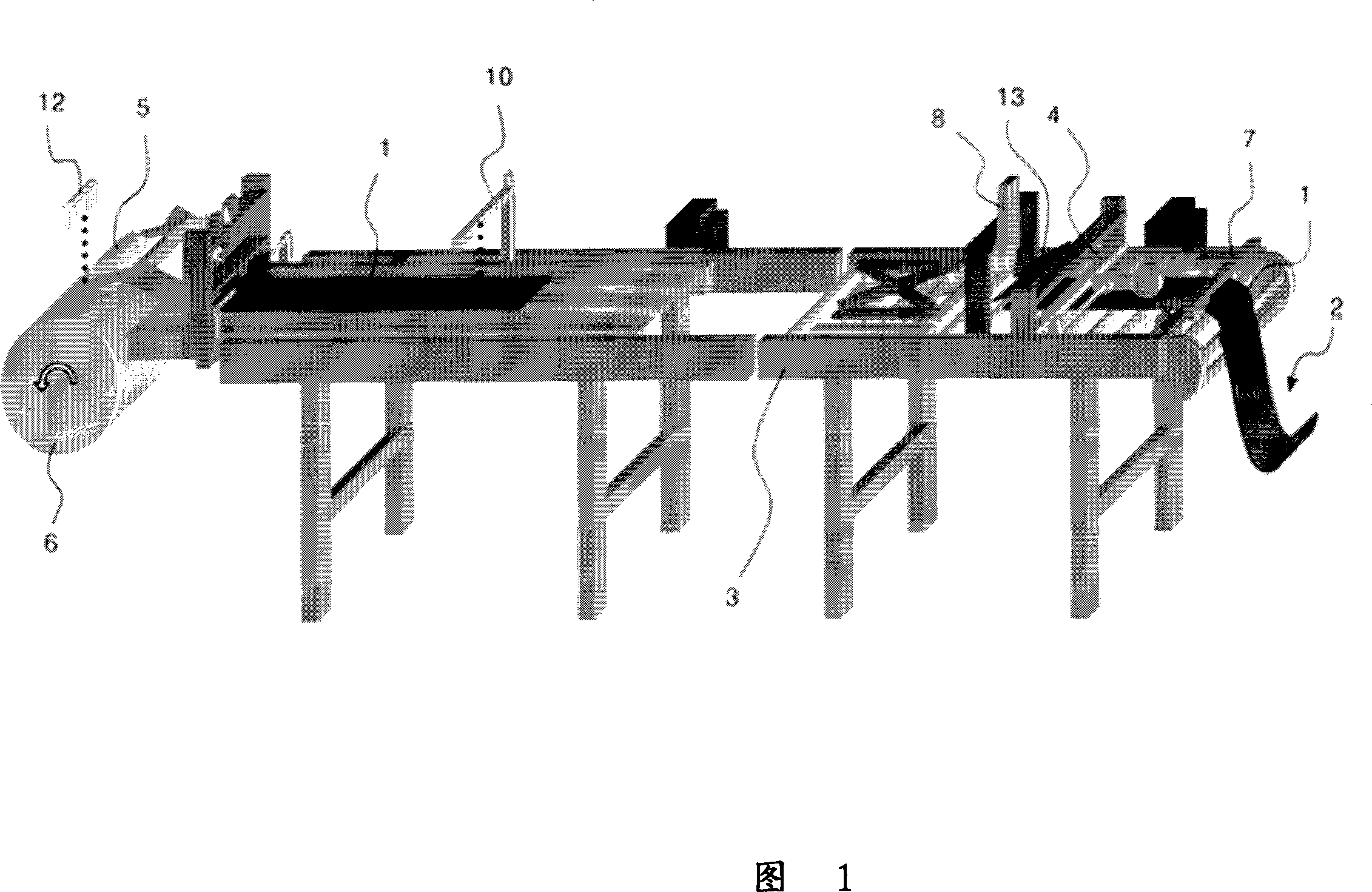
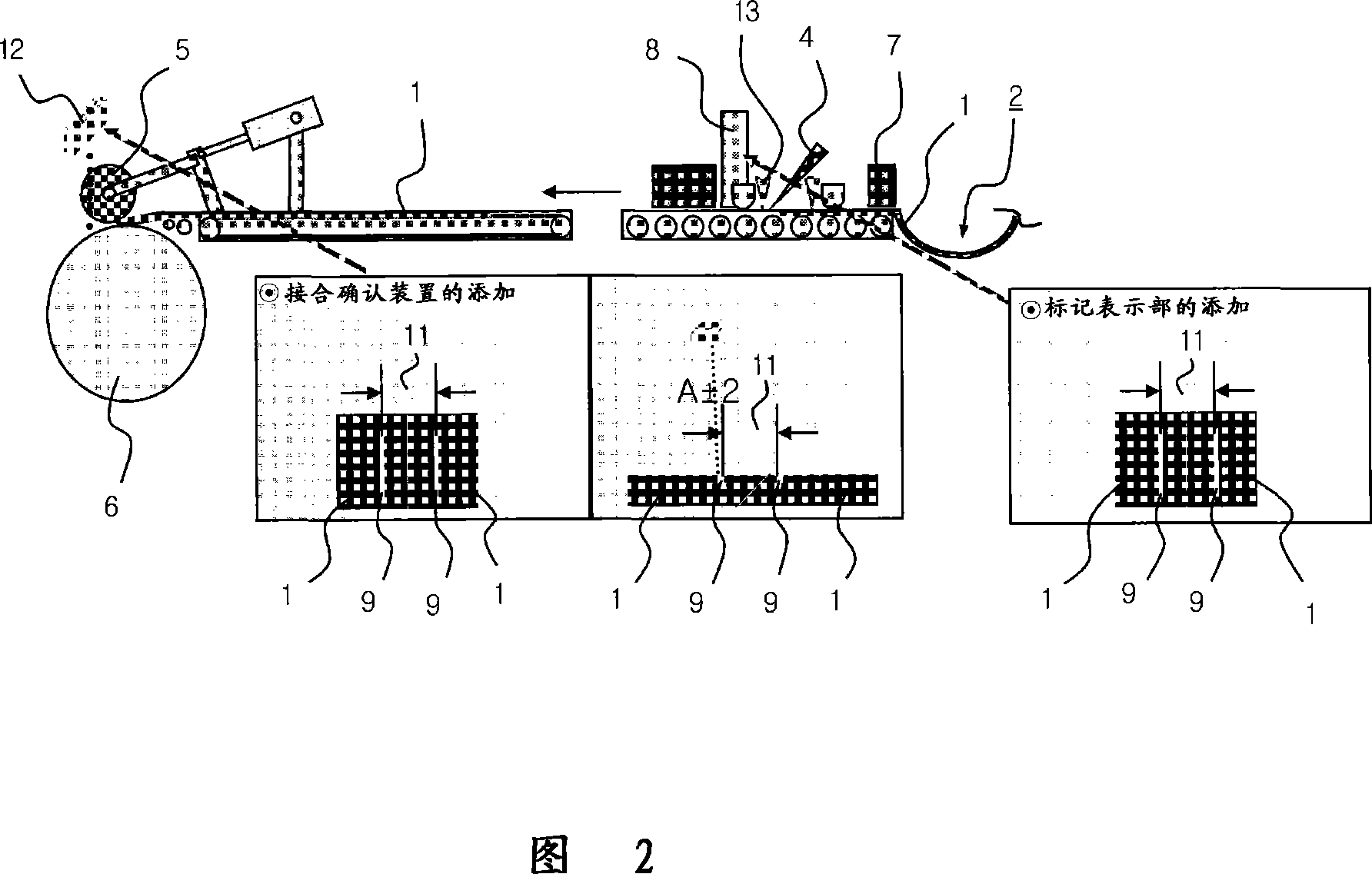
[0013] FIG. 1 is a schematic diagram showing the overall configuration of an automatic tread joining device according to the present invention, and FIG. 2 is a schematic explanatory view illustrating tread length measurement and joining operations according to the present invention.

[0014] The present invention is constituted as a tread jointing device: the tread 1 rolled on the trolley is thrown into the conveying conveyor belt 3 through the loop 2, and after being cut at a predetermined length by the cutting part 4, it is rolled up by the squeeze roller 5. On the forming belt cylinder 6 and joining, in which the width guide part 7 for guiding the initial width of the tread 1 is provided on the front side of the above-mentioned cut part 4, and the marking part is provided on the rear side of the above-mentioned cut part 4, respectively. 8. A length measuring part 10 is provided between the above-mentioned marking part 8 and the forming belt cylinder. The length measuring par...


PUM


Abstract

An automatic thread splicing apparatus is provided to cut the thread of tyre semifinished product wound on the trolley into a predetermined length to wind on a molding belt drum. A thread is supplied to a convey belt through a loop unit, and cut into a predetermined length by a cutter unit. The cut thread passes through a compression roll, and is wound onto a molding belt drum and spliced. A width guide unit for guiding the initial width of the thread is arrange in front of the cutter unit, and a marking unit is arrange in rear of the cutter unit. A length measurement unit is interposed between the marking unit and the molding belt drum so as to measure the length of the cut thread and has a marked portion formed by the marking unit. A splicing checking unit is spaced apart from the molding belt drum so as to check the splicing interval of the thread wound on the molding belt drum.

Description

technical field [0001] The present invention relates to an automatic tread joining device that cuts a tire tread that is a semi-finished tire rolled on a trolley to a predetermined length and rolls it on a forming belt cylinder, and more specifically, relates to improving the performance of tires by automating the entire operation Automatic tread joining device with labor saving and uniform quality. Background technique [0002] The so-called tire tread refers to the part of the tire that is in direct contact with the road surface. After such a tread is extruded with a specified length in the extruder and stored, when the tire is formed, in order to improve the efficiency of the forming operation , the tread is joined by a tread joining device, that is to say, the existing tread joining device as shown in FIG. Throwing into the conveying conveyor belt 103, then the cut portion 104 is cut into a length unit around the forming belt cylinder 106 and moves, and is supplied afte...

Claims


Application Information

Patent Timeline
IPC IPC(8): B29C65/74B29C65/00
CPCB29D30/30B29D30/58B29D30/68B29D2030/3085
Inventor 李明基李贤镐
Owner HANKOOK TIRE WORLDWIDE
Why Eureka
Try Eureka