Ink-jet printing head, liquid spraying device and its pressure modulating unit and regulating method

A technology of modulation unit and adjustment method, applied in printing and other directions, can solve the problems of small pressure control range, easy material deterioration of air bags, long assembly time, etc., and achieves the effects of high reliability, easy assembly and few components.

Inactive Publication Date: 2008-03-19
IND TECH RES INST
View PDF1 Cites 7 Cited by
  • Summary
  • Abstract
  • Description
  • Claims
  • Application Information

AI Technical Summary

Problems solved by technology

[0003] However, the assembly process of the above-mentioned inkjet print head 1 is extremely complicated, and the assembly time is too long, and the air bag 10 is limited by the inner space of the inkjet print

Method used


Image

  • Ink-jet printing head, liquid spraying device and its pressure modulating unit and regulating method
  • Ink-jet printing head, liquid spraying device and its pressure modulating unit and regulating method
  • Ink-jet printing head, liquid spraying device and its pressure modulating unit and regulating method

Examples


Embodiment Construction

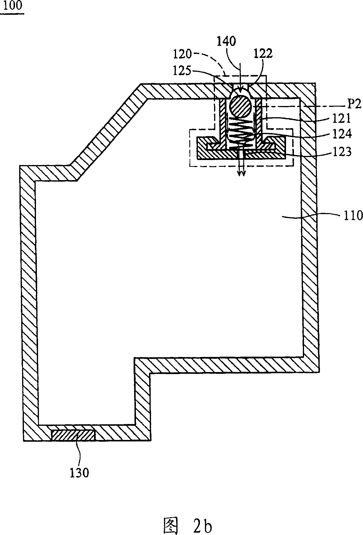
[0051] Referring to FIG. 2 a and FIG. 2 b , it shows the inkjet print head 100 according to the first embodiment of the present invention, including a cavity 110 , a pressure modulation unit 120 and a nozzle 130 . The pressure modulation unit 120 is disposed in the cavity 110 and communicates with the cavity 110 . The pressure modulation unit 120 includes a housing 121 , an air inlet 122 , an air outlet 123 , an elastic mechanism 124 and a sealing block 125 . The intake port 122 is opened on the surface of the cavity 110 . The air outlet port 123 is opened on the surface of the casing 121 . The sealing block 125 is connected to the elastic mechanism 124 . The elastic mechanism 124 abuts against the casing 121 . The elastic mechanism 124 moves the sealing block 125 between a first position P1 (refer to FIG. 2 a ) and a second position P2 (refer to FIG. 2 b ) through elastic force. Referring to FIG. 2 a , when the sealing block 125 is located at the first position P1 , the s...


PUM


Abstract

The invention discloses an inkjet printing head and includes a cavity and a pressure modulation unit. The pressure modulation communicates the cavity. The pressure modulation unit comprises an air-in port, an air-out port, an elastic body and a sealed block connecting the elastic body. The elastic body makes the sealed block move between a first position and a second position through elasticity. When the sealed block is at the first position, the sealed block seal the air-in port; when the sealed block is at the second position, an airflow passes by the air-in port, then passes by the pressure modulation unit and enters into the cavity through the air-out port.

Description

technical field [0001] The invention relates to an inkjet printing head, in particular to an inkjet printing head with high reliability. Background technique [0002] Referring to FIG. 1 , it shows an inkjet print head 1 disclosed in US Pat. No. 6,213,598, including an air bag 10 , a side plate 20 , a spring 30 , a reed 40 , and a steel ball 50 . The air bag 10 is connected to the atmosphere through the air bag connection hole 11, so that the outside air smoothly flows into the air bag 10 in the inkjet print head, and the air bag 10 is expanded. At this time, the spring 30 is compressed at the same time. When the compressed distance When the side plate 20 pushes against the reed 40, the negative pressure in the inkjet print head also reaches a certain negative pressure value. At this time, the outside atmosphere smoothly pushes the steel ball 50 away through the air inlet 51, allowing air to enter the inkjet print head. In the print head, the negative pressure in the inkjet...

Claims


Application Information

Patent Timeline
IPC IPC(8): B41J2/175
Inventor 林顺泉何美祺徐维良周柏甫
Owner IND TECH RES INST
Why Eureka
Try Eureka