Vane cell pump

A vane pump and vane technology, applied in the pump, pump control, rotary piston pump and other directions, can solve the problems of high manufacturing cost and complex structure of the pendulum slide valve pump, and achieve the effect of easy installation and sensitive adjustment

Inactive Publication Date: 2008-03-19
JOMA POLYTEC
View PDF2 Cites 8 Cited by
  • Summary
  • Abstract
  • Description
  • Claims
  • Application Information

AI Technical Summary

Problems solved by technology

But the pendulum valve pump known from DE 195 32 703 C1 i...

Method used


Image

  • Vane cell pump
  • Vane cell pump
  • Vane cell pump

Examples


Embodiment Construction

[0028] For a better understanding of the invention, reference is made to DE 10 2005 048 602, the content of which forms part of this description.

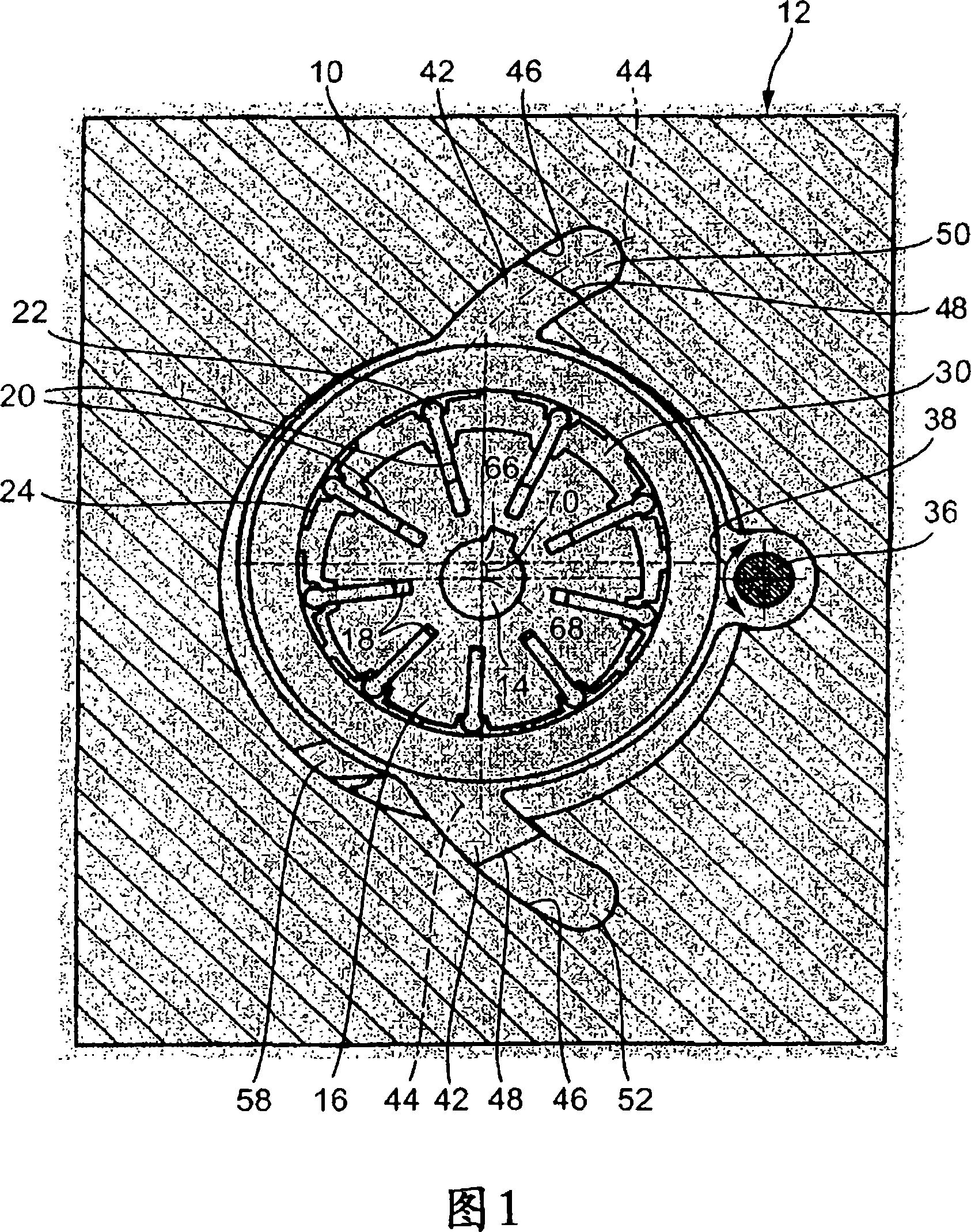
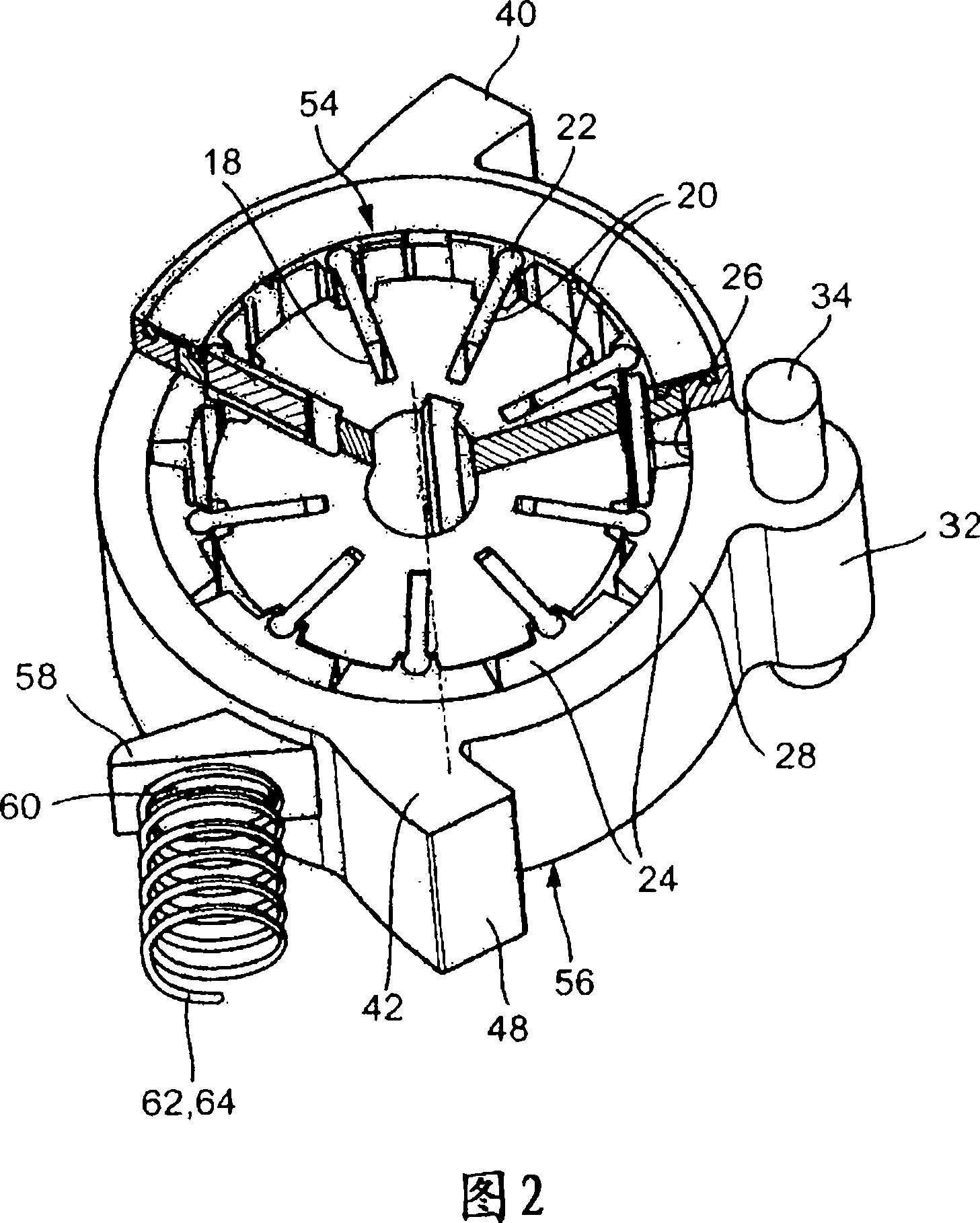
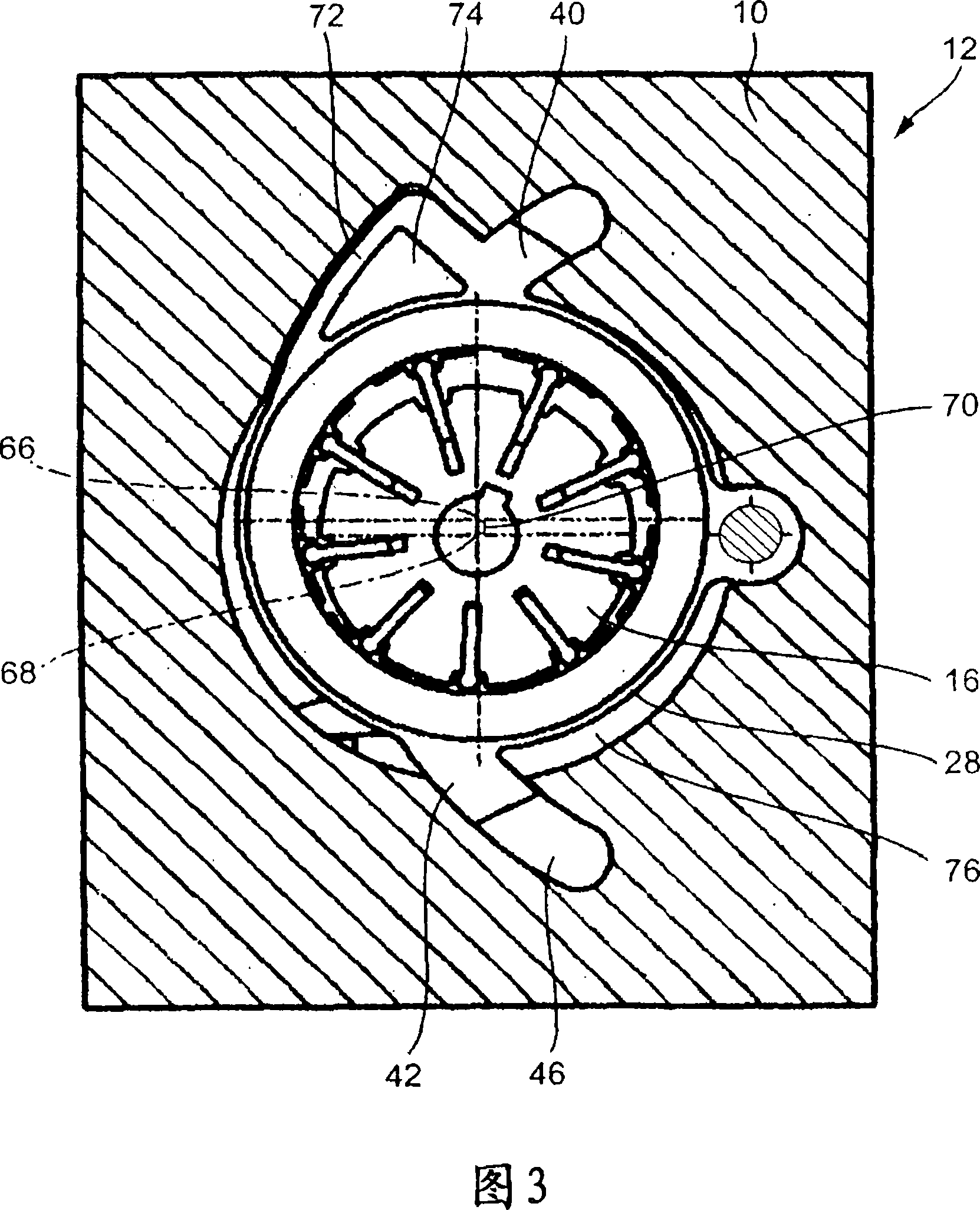
[0029] Fig. 1 schematically shows a housing 10 of a vane pump, generally designated 12, within which a drive shaft 14 is mounted. The drive shaft 14 drives an inner rotor 16 having a plurality of slots 18 in which vanes 20 are radially movably mounted. These blades 20 have thickened ends 22 to which guide blocks 24 are pivotally attached. As can be clearly seen in FIG. 2 , the guide block 24 rests on the inner circumferential surface 26 of the stator 28 . The inner rotor 16 , the two blades 20 , the two guide blocks 24 and the stator 28 respectively form a working space 30 . As the inner rotor 16 turns, the working space 30 expands and contracts, allowing fluid transfer.

[0030] Furthermore, as can be clearly seen in FIGS. 1 and 2 , the stator 28 has bearing lugs 32 which surround a pivot 34 and form a pivot bearing 36 which is...


PUM


Abstract

The invention relates to a vane pump (12) comprising an inner rotor (16) and a plurality of vanes (20) mounted substantially radially movably radially within the inner rotor in the slot (18), and directed directly or indirectly on the inner circumferential surface (26) of the stator (28). The axes of the stator and the inner rotor are offset relative to each other, and the stator (28) can be adjusted radially relative to the inner rotor (16) and thus the offset can be varied. The stator (28) includes a pivot bearing (36) disposed within the housing of the vane pump. At least one piston part (42) protrudes from the stator, whereby a piston axis (44) of said piston part extends circumferentially relative to said pivot bearing (36).

Description

technical field [0001] The invention relates to a vane pump having an inner rotor and a plurality of vanes mounted radially movably within the inner rotor, substantially in radial slots and directly or indirectly in is guided on the inner circumferential surface of the stator. The axis of the stator and the axis of the inner rotor are offset relative to each other, and the stator is radially adjustable relative to the inner rotor so that the offset can be changed. The stator includes pivot bearings disposed within the housing of the vane pump. Background technique [0002] A vane pump with an annular inner rotor is known from DE 100 40 711 A1, in which a plurality of radially outwardly extending vane elements are accommodated so as to be displaceable in the radial direction. The radially inner ends of the blade elements rest on the torsion-proof central part, and the radially outer ends rest on the torsion-proof outer ring. The rotor is rotatable about an axis of rotation...

Claims


Application Information

Patent Timeline
IPC IPC(8): F04C14/22
CPCF04C14/226F04C2/3445F04C2/3442
Inventor 维利·施奈德
Owner JOMA POLYTEC
Why Eureka
Try Eureka