Pressure state display device

A state display and pressure technology, applied in the direction of measuring devices, measuring fluid pressure, piston type fluid pressure measurement, etc., can solve the problems of poor identification, inability to judge whether the pressurized fluid is supplied, and installation of multiple pipe joints, etc.

Inactive Publication Date: 2008-03-19
KOGANEI
View PDF3 Cites 5 Cited by
  • Summary
  • Abstract
  • Description
  • Claims
  • Application Information

AI Technical Summary

Problems solved by technology

[0010] When mounting a plurality of pipe joints on a fluid pressure mechanism, since each pipe joint must be installed while securing the size of the display portion protruding radially outward from the joint body, it is not possible to install multiple pipe joints in a limited space. pipe joints, so that the fluid pressure mechanism equipped with pipe joints has to be enlarged
In order to reduce the size of the display unit and avoid an increase in the size of the fluid pressure mechanism, the displacement of the display member can be set to be small when the pressurized fluid is supplied and when the pressurized fluid is not supplied, but this will make it difficult to confirm visually. If there is fluid, there may be misoperation to pull out the tube from the tube fitting while the pressurized fluid is being supplied.
On the other hand, as described in Patent Document 3, in the case of displaying the pressure state corresponding to the position of the piston, it is necessary to always observe the piston from the outside through a transparent tube, and it is impossible to judge whether the pressurized fluid is is supplied, so there is a problem of poor recognition

Method used


Image

  • Pressure state display device
  • Pressure state display device
  • Pressure state display device

Examples


Embodiment Construction

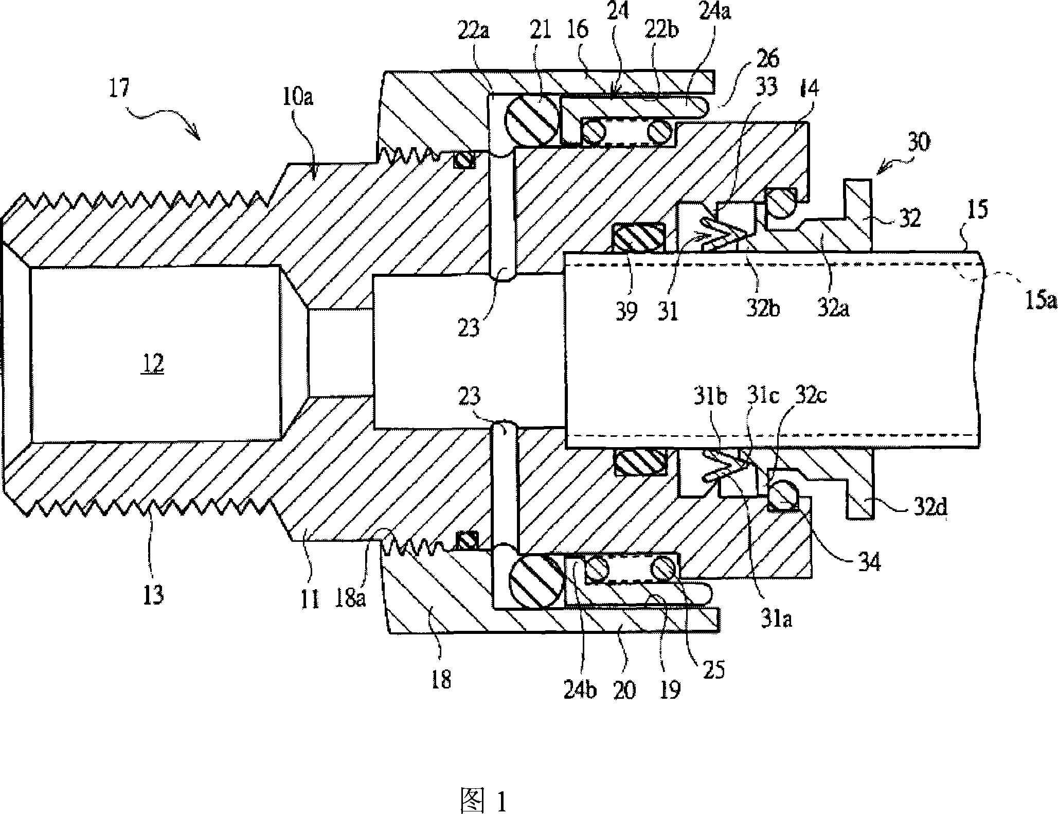
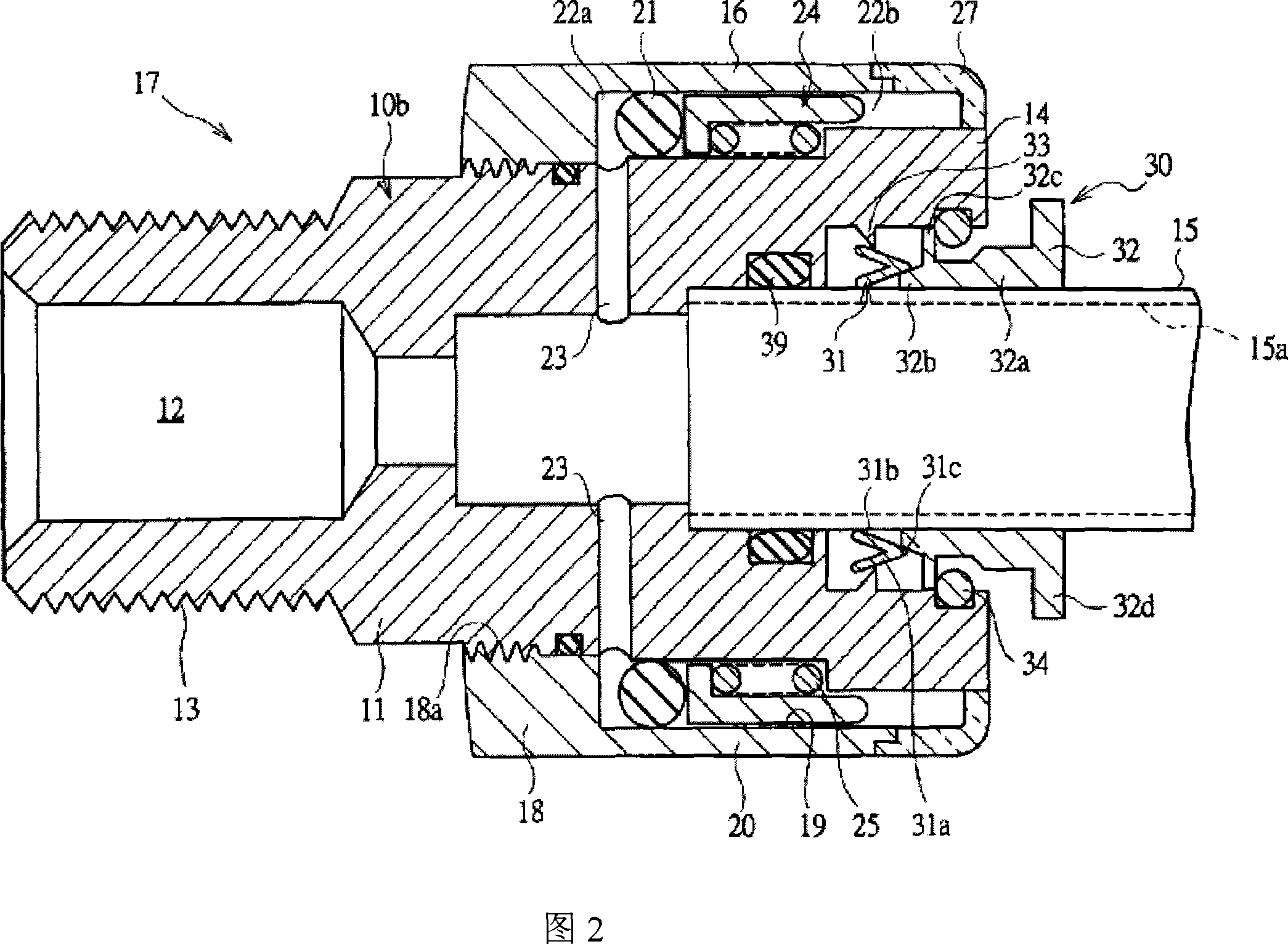
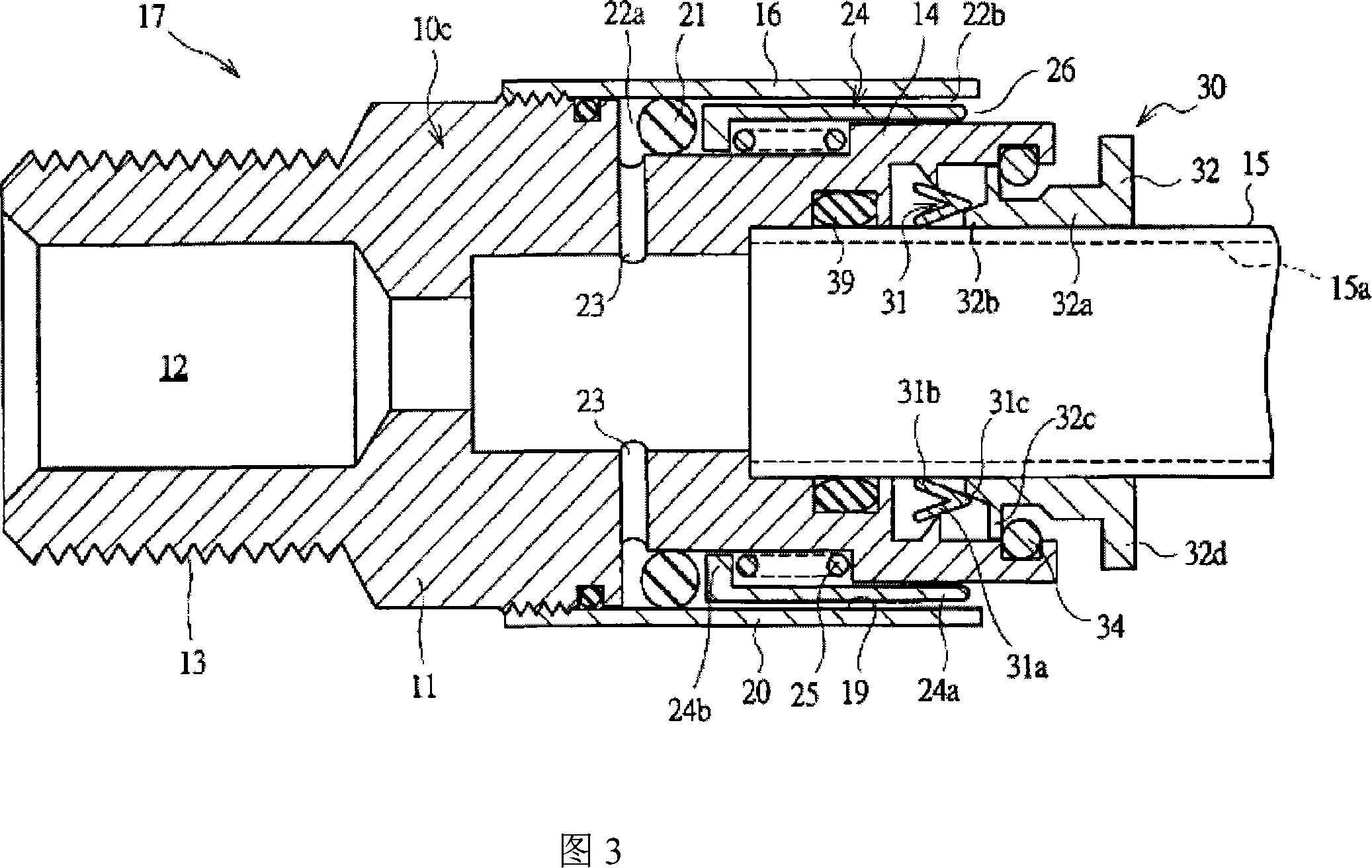
[0044] Hereinafter, the present invention will be described in detail according to the embodiments of the present invention. In different embodiments, the same reference numerals are used to denote the same components.

[0045] The pipe joint 10a shown in FIG. 1 is of a linear type, and is installed on a control mechanism or a fluid pressure working mechanism that constitutes a fluid pressure circuit, and is used to guide compressed air. The pipe joint 10 a has a stepped cylindrical joint body 11, and a fluid flow path 12 for guiding compressed air is formed through the inside of the joint body 11. The base end side of the joint body 11 is provided with an external thread 13 for attaching the pipe joint 10a to a control mechanism or a fluid pressure operating mechanism, etc., and the fluid tube 15 is detachably connected to a connecting end 14 on the front end side. on. The fluid tube 15 is formed of a flexible material composed of soft resin such as nylon and urethane. If the flu...


PUM


Abstract

A pressure status display device displays whether positive pressure fluid or negative pressure fluid is being supplied in a fluid channel. A fluid guiding member (17) is constructed from a coupling body (11) where a fluid channel (12) is formed and from a partition member (16) provided outside the coupling body (11), and a receiving space (19) is formed by the partition member (16) and the coupling body (11). A pressure chamber (22a) communicating with the fluid channel (12) via a communication hole (23) is formed in the receiving space (19) by a sliding seal member (21) provided in the receiving space (19). When pressure is not being supplied to the fluid channel (12) by a spring member (25), a sliding sleeve (24) is positioned at a non-supply position, and when pressure is supplied, the sliding sleeve (24) moves to a supply position. The pressure status in the fluid channel (12) can be confirmed from the outside by observing the positions of the sliding seal member (21) and the sliding sleeve (24).

Description

Technical field [0001] The present invention relates to a pressure state display device for externally displaying whether a fluid is supplied into a fluid flow path. Background technique [0002] The fluid pressure circuit for supplying compressed air from a compressed air source to a fluid working mechanism such as a pneumatic cylinder is provided with a pressure control valve that adjusts the pressure of the compressed air and a directional control valve that switches the flow path. The control mechanism uses fluid pipes such as pipes for connecting the various components constituting the fluid pressure circuit to each other. In the fluid pressure circuit for supplying the liquid pressurized by the pressurizing source to the fluid pressure operating mechanism, fluid pipes such as pipes for connecting the various components constituting the fluid pressure circuit to each other are also used. A fluid pipe can also be used in a fluid pressure circuit for supplying negative pressur...

Claims


Application Information

Patent Timeline
Patent Type & Authority Applications(China)
IPC IPC(8): F16L55/00G01L7/00G01L7/16
CPCG01L19/10G01L19/0023G01L7/166G01L19/12F16L37/091F16L37/0915F16L55/00G01L7/00G01L7/16
Inventor 佐藤浩
Owner KOGANEI
Why Eureka
Try Eureka