1D or 2D goniometry method of diffuse sources

A technology of angle measurement and diffuser, applied in direction finders using radio waves, directional multi-channel systems using radio waves, etc., to achieve the effect of reducing computational overhead

Inactive Publication Date: 2008-03-19
THALES SA
View PDF0 Cites 2 Cited by
  • Summary
  • Abstract
  • Description
  • Claims
  • Application Information

AI Technical Summary

Problems solved by technology

However, the proposed angle determination algorithm is only in azimuth: 1D

Method used


Image

  • 1D or 2D goniometry method of diffuse sources
  • 1D or 2D goniometry method of diffuse sources
  • 1D or 2D goniometry method of diffuse sources

Examples


Embodiment Construction

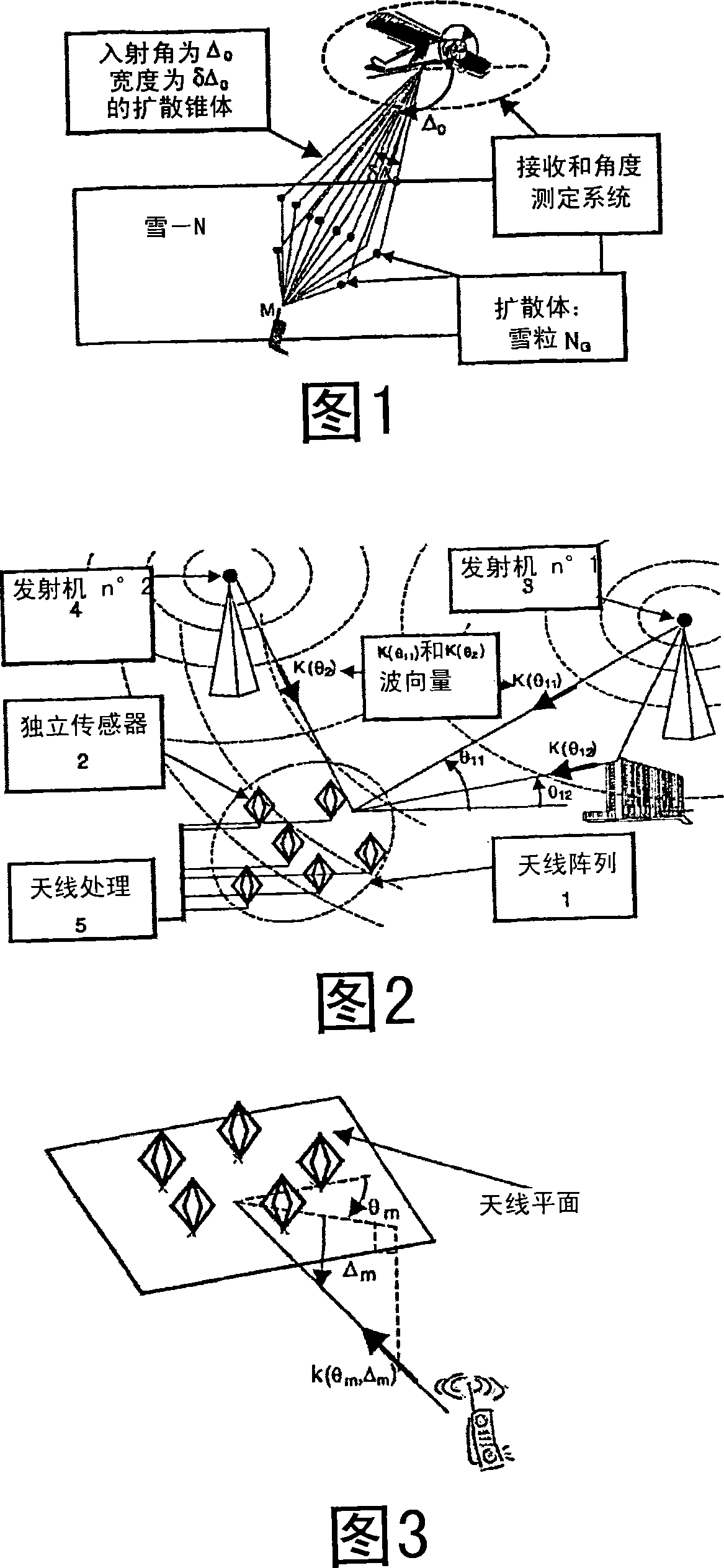
[0043] For a better understanding of the method according to the invention, the following description is given, as shown, without limitation, where, as represented for example in FIG. . Snow particles act as diffusers.

[0044] In this example, for example, a diffuse or distributed source is characterized by its direction and a cone of diffusion.

[0045] Before describing the exemplary embodiments in detail, some hints are given which are helpful in understanding the method according to the invention.

[0046] generally

[0047] Along the incident (θ mp ρ of m In the case of a non-distributed multiplex to propagate M transmitters, the following observation vector x(t) is received at the output of the sensor:

[0048]

[0049] where x n (t) is the signal received on the nth sensor, is the incident angle θ from the sensor array, The response of the source, s m (t) is the signal sent by the mth transmitter, τ mp ,f mp A and ρ mp are the delay, Doppler shift, and...


PUM


Abstract

A goniometry method for one or more diffuse ( or distributing) sources, characterized by one or more given directions and a propagation cone, and received by an array of several sensors. The method is characterized in that including at least the following steps: a) breaking down the propagation cone into a finite number L of diffusers with parameters (Theta mp, Delta Theta mpi, Delta mp, Theta Delta mpi) associated to the diffusers; b) combining the direction vector a(Delta mp + Delta Delta mpi, Delta mp +Delta Delta mpi) associated to the number L of diffusers, to obtain vector D((Theta, Delta, Delta Theta, Delta Delta)Alpha or U(Delta, Delta)Beta(Delta Theta, Delta Delta, Alpha)) determined by at least one of incident angle and angular deflection parameter (Theta, Delta, Delta Theta, Delta Delta) as well as a combined vector Alpha; c) applying MUSIC type rule or arbitrary other angular measuring algorithm to the vector D((Theta, Delta, Delta Theta, Delta Delta)Alpha or U(Delta, Delta)Beta(Delta Theta, Delta Delta, Alpha)), so as to confirm at least one of incident angular parameters Theta mp, Delta mp, Delta Delta mp, Delta Theta mp of the propagation cone.

Description

technical field [0001] The present invention relates to goniometric methods for one or more diffuse, or "distributed" radio frequency sources, where a receiver treats a source in a given direction as a diffuse cone of specified width and average angle of incidence. Background technique [0002] In particular, a distributed source is defined as a source that propagates through a continuum of diffusers. [0003] In particular, the invention makes it possible to position one or more distributed radio frequency sources angularly and / or azimuthally. For example, the aim is to determine the central incidence angle of the diffusing cone and the width of the cone. [0004] One-dimensional, 1D, or two-dimensional, 2D goniometric measurements are generated, where the 1D goniometric measurements parametrically represent the angle of incidence by the azimuth angle, and the incident angles of the 2D goniometric measurements depend on azimuth and altitude parameters. [0005] For exampl...

Claims


Application Information

Patent Timeline
Patent Type & Authority Applications(China)
IPC IPC(8): G01S3/74
CPCG01S3/74
Inventor A·费雷奥尔B·维贝尔P·莫尔冈
Owner THALES SA
Why Eureka
Try Eureka