

Bed load detector
A detector and detection sensor technology, which is applied in the direction of instruments, hospital beds, alarms, etc., can solve the problems of difficulty in occupying the main body of the bed and difficulty in unloading work
- Summary
- Abstract
- Description
- Claims
- Application Information
AI Technical Summary
Problems solved by technology
Method used
Image

Examples
Embodiment Construction
[0130] In the following figures, some preferred embodiments of the invention are illustrated by way of example and not limitation. It should be appreciated that numerous other modifications to these illustrated embodiments may be made by those skilled in the art based on the present disclosure.
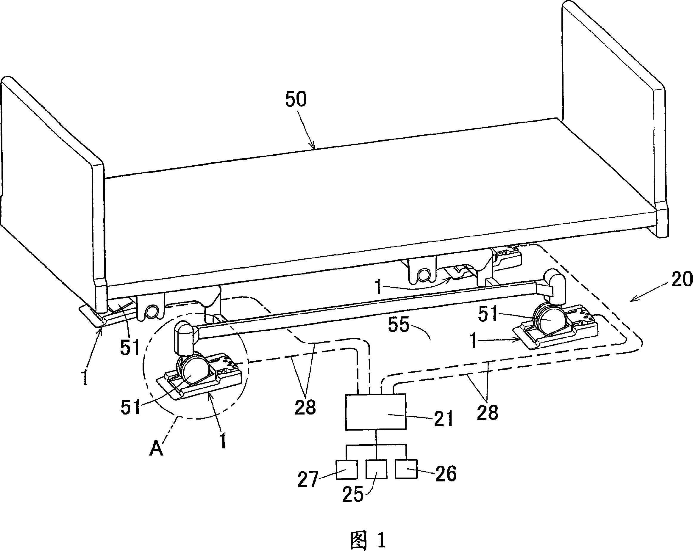
[0131] In FIG. 1 , reference numeral "1" denotes a bed load detector according to a first embodiment of the present invention, and reference numeral "20" denotes a bed occupancy detection device according to an embodiment of the present invention. And reference numeral "50" denotes a bed.
[0132] The bed 50 is used in medical institutions such as hospitals, institutes for the elderly, nursing institutions, ordinary homes, etc., and is formed in a rectangular shape as shown from the top. The bed 50 has a plurality of leg sections. Specifically, it has a total of four leg sections, namely, a leg section on the left side of the head of the main body (not shown), a leg section on the r...
PUM
 Abstract
Description
Claims
Application Information