
Vacuum cleaner electric motor air-out door bridging structure

A technology for air suction vents and vacuum cleaners, which is applied to vacuum cleaners, cleaning equipment, household appliances, etc. It can solve the problems of interfering with the vortex airflow suction effect and reduce the suction rate of the suction port, so as to improve the suction rate and facilitate the continuation of the effect

Inactive Publication Date: 2008-03-26
LG ELECTRONICS (TIANJIN) APPLIANCES CO LTD
View PDF0 Cites 0 Cited by
  • Summary
  • Abstract
  • Description
  • Claims
  • Application Information

AI Technical Summary

Problems solved by technology

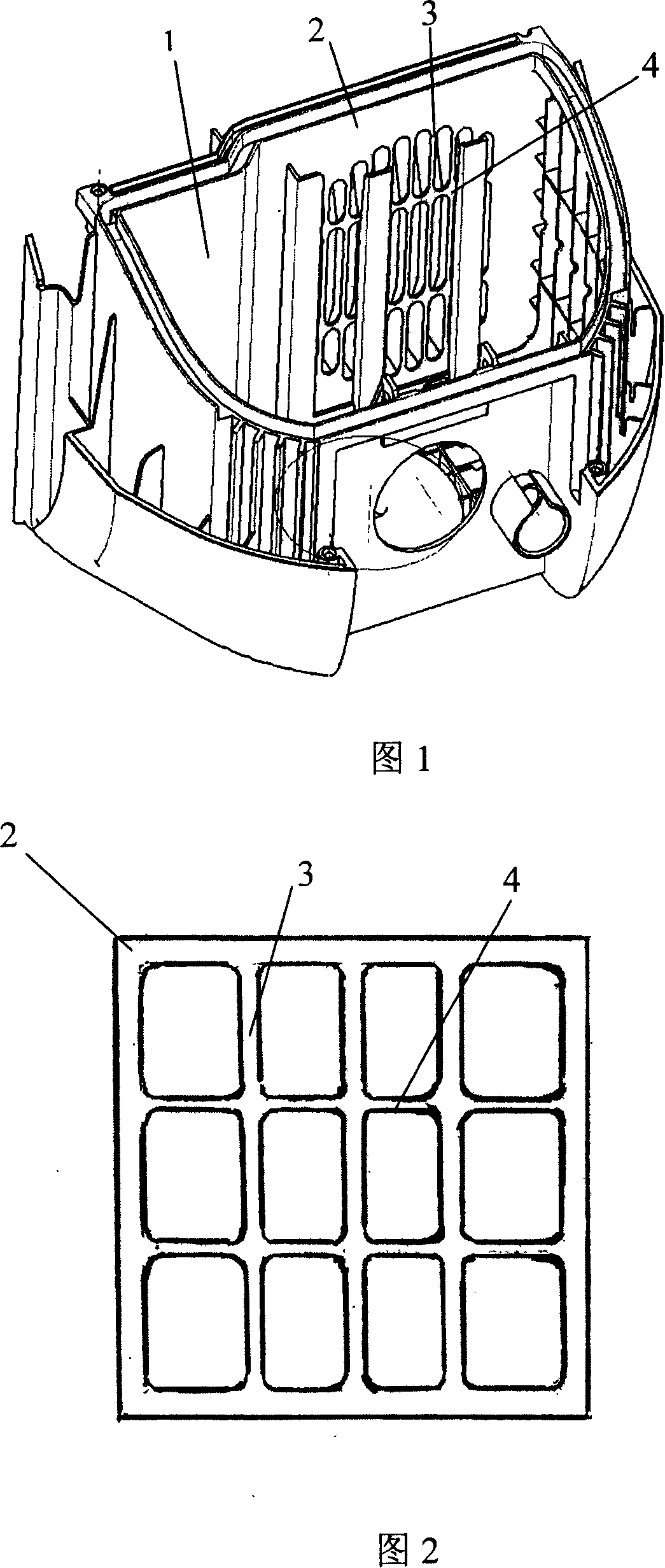
[0007] However, the air intake of the common vacuum cleaner motor compartment is formed in a circular shape, while the air intake joist is composed of a rectangular joist frame and joist ribs and connecting ribs formed perpendicular to each other on it, and the circular air intake forms a vortex. Airflow, the rectangular joists interfere with the suction effect of the vortex airflow, reducing the suction rate of the suction port

Method used


Image

  • Vacuum cleaner electric motor air-out door bridging structure
  • Vacuum cleaner electric motor air-out door bridging structure

Examples


Embodiment Construction

[0019] In order to further understand the invention content, characteristics and effects of the present invention, the following examples are given, and detailed descriptions are as follows in conjunction with the accompanying drawings:

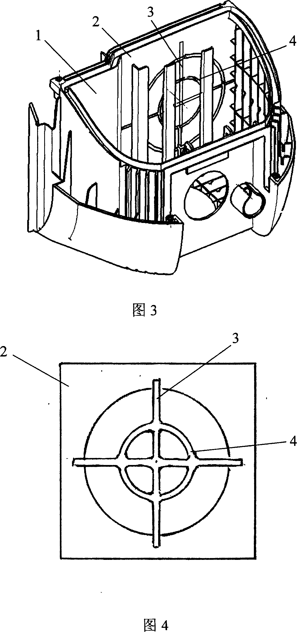
[0020] Fig. 3 is a schematic diagram of the position of the joist of the motor air outlet according to the embodiment of the present invention; Fig. 4 is a schematic diagram of the joist of the motor air outlet according to the embodiment of the present invention.

[0021] Referring to accompanying drawing 3: a kind of joist structure of vacuum cleaner motor suction outlet, comprises the joist frame 2 that forms shape, the joist rib 3 that supports joist frame and the connecting rib 4 that connects joist rib; joist frame 2 is hollow circular Forming, the joist ribs 3 are formed radially toward the circular edge of the joist frame 2 with the circular center point of the joist frame 2 as the center.

[0022] Referring to accompanying drawing 4:...


PUM


Abstract

The present invention belongs to a vacuum cleaner with a drive tool capable of making dust be loosened, in the concrete, it relates to a vacuum cleaner motor suction opening grid structure. It includes grid frame formed into its external form, grid rib for supporting grid frame and connection rib for connecting with grid rib. The suction opening grid is circularly fixed on the motor suction opening, so that the suction rate of the suction opening can be greatly raised.

Description

technical field [0001] The invention relates to a joist structure of an air suction port of a vacuum cleaner motor for driving a dust loosening tool, in particular to a joist structure of an air suction port of a vacuum cleaner motor which improves the suction rate of the air suction port. Background technique [0002] The vacuum cleaner is a cleaning and sanitary appliance used to remove dust from floors, carpets, walls, furniture, clothing and various gaps. [0003] The general structure of the vacuum cleaner includes a vacuum cleaner motor that generates suction by introducing an electric current, a suction nozzle, a suction pipe, a filter device that form an air path system, and a dust collection part that collects inhaled objects. [0004] In order to adapt to the cleaning of different cleaning surfaces or corners, the usual vacuum cleaner nozzles can have different shapes and uses, such as tapered nozzles, rectangular vacuum cleaner brushes, etc. for optional use. [...

Claims


Application Information

Patent Timeline
IPC IPC(8): A47L9/00
Inventor 高岩
Owner LG ELECTRONICS (TIANJIN) APPLIANCES CO LTD
Learn More