Clay vibrating bunker

A vibrating hopper and clay technology, applied in vibrating conveyors, loading/unloading, conveyors, etc., can solve problems such as uneven feeding, blockage, and material accumulation at the outlet, and achieve the effect of smooth feeding

Inactive Publication Date: 2008-03-26
JIANGSU WANLI MACHINERY
View PDF0 Cites 18 Cited by
  • Summary
  • Abstract
  • Description
  • Claims
  • Application Information

AI Technical Summary

Problems solved by technology

[0002] In the existing clay vibrating hopper, the discharge of the material at the discharge port is only through vibration to make the material fall

Method used


Image

  • Clay vibrating bunker

Examples


Embodiment Construction

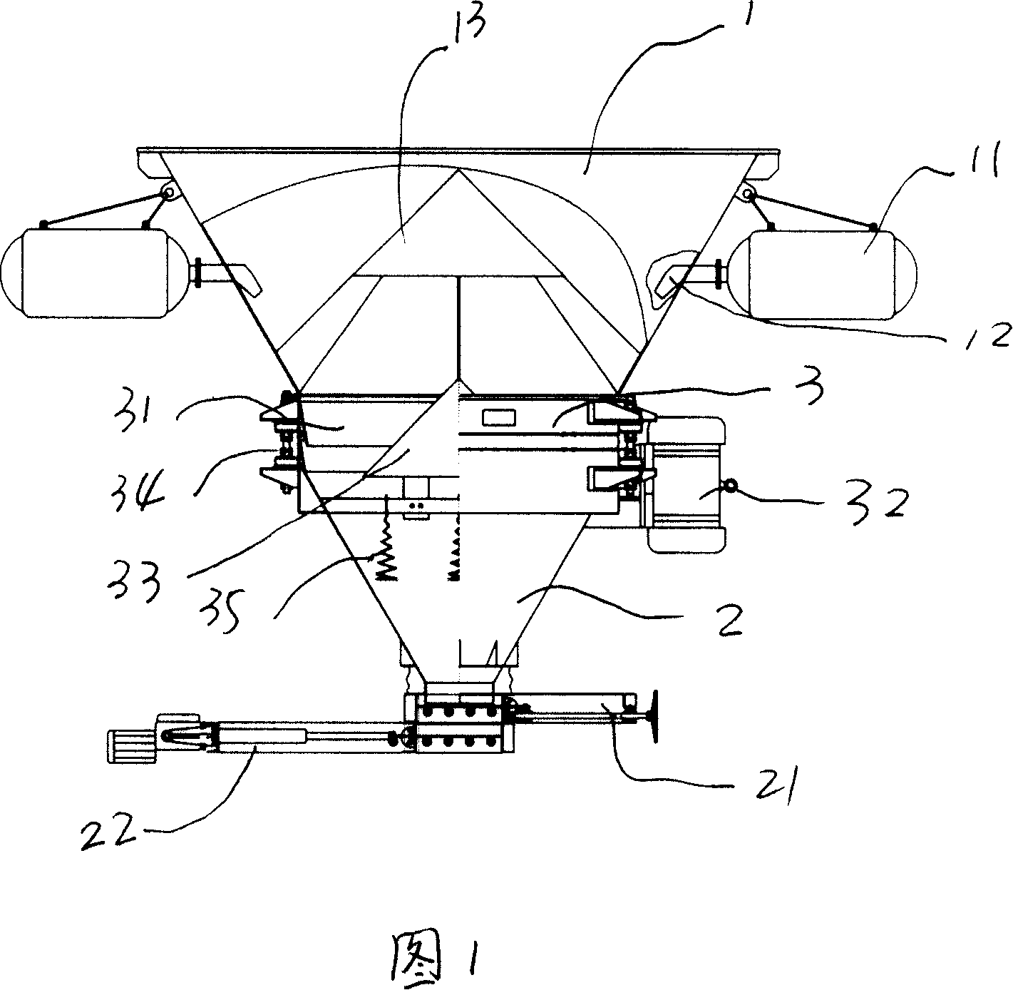
[0013] The clay vibrating hopper of the present invention will be further described below in conjunction with the accompanying drawings.

[0014] As shown in Figure 1, a vibrating hopper for clay comprises an upper cone 1 and a lower cone 2. The difference is that a vibrating device 3 is placed between the upper cone 1 and the lower cone 2. An air cannon 11 is provided, the nozzle 12 of the above-mentioned air cannon 11 is placed on the inner wall of the upper cone 1, the nozzle 12 of the above-mentioned air cannon 11 is tangent to the inner wall of the upper cone 1, and the lower part of the lower cone 2 is equipped with a manual valve 21 and an electric valve. The valve 22, the above-mentioned upper cone 1 is built with an upper cone decompression cone 13, so that the material enters the vibrating device along the inner wall of the cone.

[0015] Above-mentioned vibrating device 3 comprises vibrating hopper 31, vibrating motor 32, activation cone 33, and above-mentioned acti...


PUM


Abstract

The clay vibrating bin includes one upper cone, one lower cone, one vibrating unit set in between the upper cone and the lower cone. The upper cone has one air gun with nozzle in the inner wall, and the lower cone has one hand valve and one electric valve in the lower part. The clay vibrating bin has fluent and homogeneous material feeding and easy cleaning.

Description

technical field [0001] The invention relates to a vibrating machine suitable for conveying viscous materials. Background technique [0002] In the existing clay vibrating hopper, the discharge of the material at the discharge port is only through vibration to make the material fall. Since the clay is easy to stick together, it is easy to accumulate material, blockage, uneven feeding, and difficult cleaning at the discharge port. Contents of the invention [0003] The technical problem to be solved by the present invention is to overcome the deficiencies in the prior art and provide a vibrating clay hopper with smooth discharging, uniform feeding and easy cleaning. [0004] The technical scheme for solving the technical problems of the present invention is: a vibrating hopper for clay, comprising an upper cone and a lower cone. The difference is that a vibrating device is placed between the upper cone and the lower cone. There is an air cannon, the nozzle of the above-ment...

Claims


Application Information

Patent Timeline
IPC IPC(8): B65D88/54B65D88/70B65G27/04B65G65/34
Inventor 夏圣伯
Owner JIANGSU WANLI MACHINERY
Why Eureka
Try Eureka