Driving motor stator water-cooling method and device

A technology for driving motors and water-cooling devices, applied in electromechanical devices, electrical components, electric components, etc., can solve problems such as increasing the maintenance workload and cost of cooling equipment, insufficient cooling of rotors and bearings, and reducing the effective diameter of stators, etc. , to achieve good cooling effect, large water capacity, and ensure the smooth flow of the waterway

Active Publication Date: 2006-05-24
CSR ZHUZHOU ELECTRIC LOCOMOTIVE RES INST
View PDF0 Cites 25 Cited by
  • Summary
  • Abstract
  • Description
  • Claims
  • Application Information

AI Technical Summary

Problems solved by technology

This method is generally used on higher-power drive motors, and fans with higher power and pressure heads must be used.
[0008] The second type is that the cooling air is blown into the surface of the motor frame, and the motor is a fully enclosed structure
[0012] The second type is: the fan is installed at the tail of the motor, the wind can only blow to the surface of the motor, and the motor is a fully enclosed structure
One is that the existing stator is water-cooled (that is, when the double-wall casing is used for cooling), the water-covered area of ​​the casing is too small, resulting in poor cooling effect, and the rotor and bearings cannot be sufficiently cooled; the other is that the existing water-cooled The power of the traction motor is relatively small, and the maximum power so far is 240KW; the third is that the sealing of the motor is relatively high; the fourth is that in the case of the same outer diameter, the effective diameter of the stator is reduced due to the cooling circuit; the other is Fifth, it is necessary to install a water / air heat exchange device, which increases the maintenance workload and cost of cooling equipment
[0019] Through the above analysis, it can be seen that the current motor water cooling method still has some shortcomings, especially in the case of limited volume of high power density motors, it is not suitable to directly apply the existing motor water cooling technology to high power density motors, so It is necessary to further improve the cooling system of the motor to increase its heat dissipation capacity

Method used


Image

  • Driving motor stator water-cooling method and device
  • Driving motor stator water-cooling method and device
  • Driving motor stator water-cooling method and device

Examples


Embodiment 1

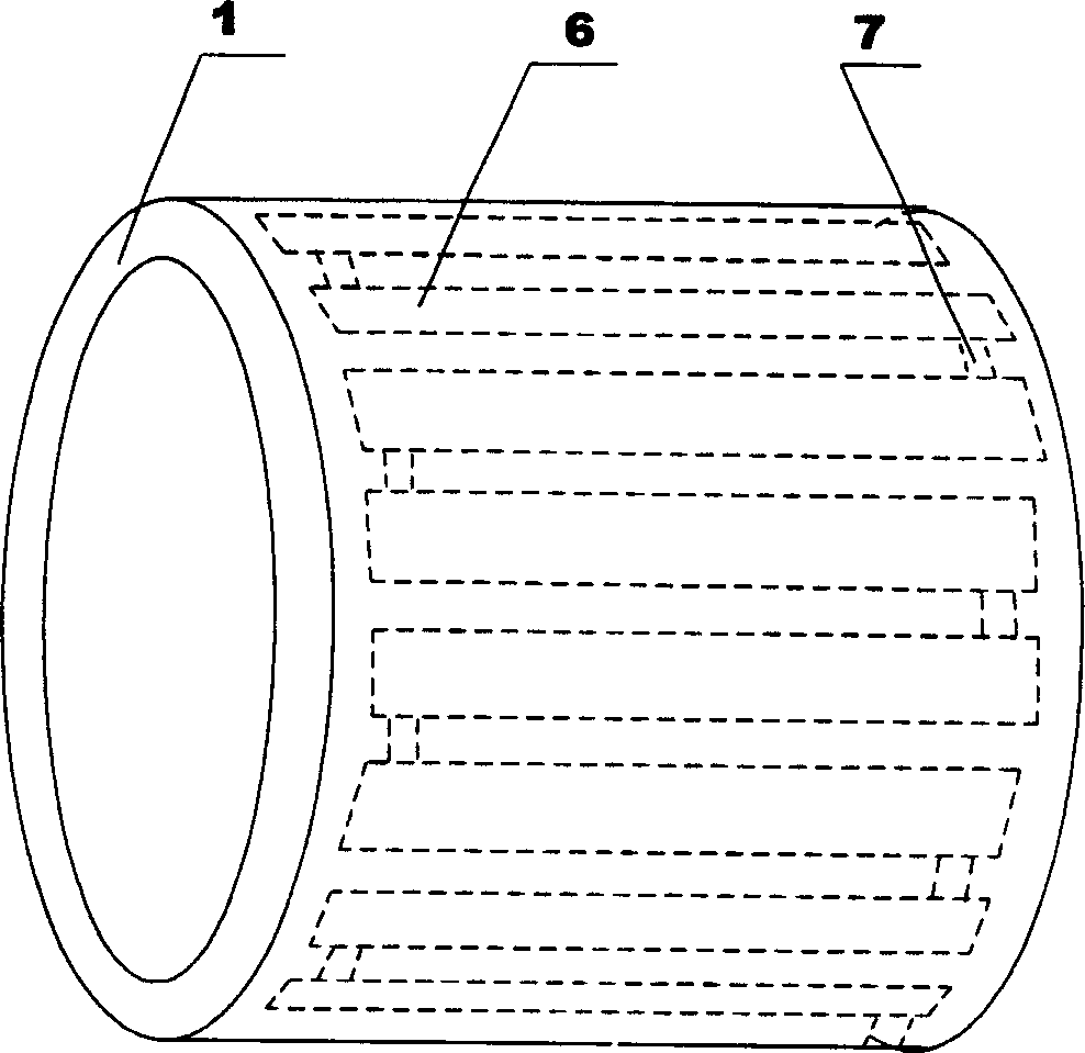
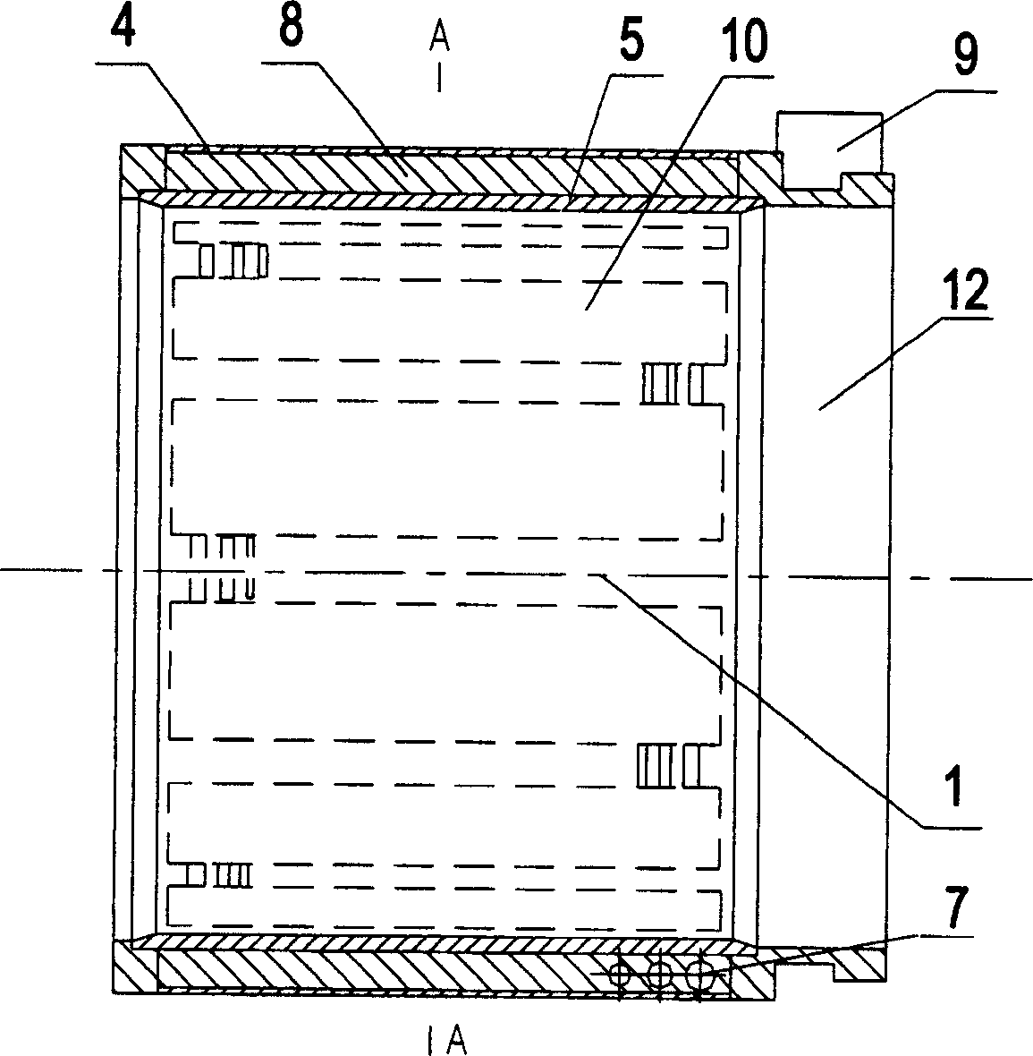
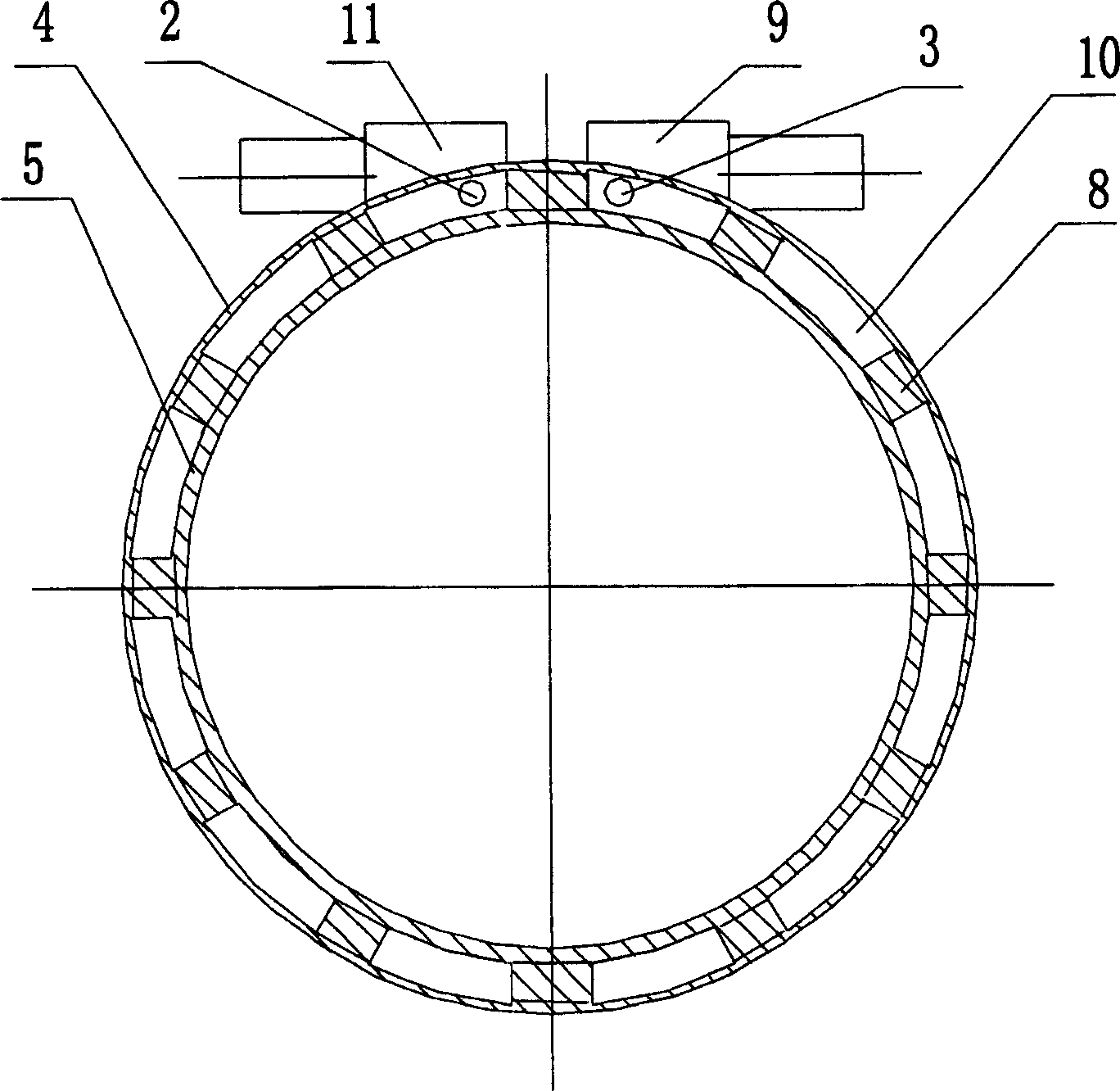
[0041] A squirrel-cage motor (such as figure 2 , 3 shown), including the stator frame 1 and the cooling channel 6, the stator frame 1 is cooled by the cooling channel 6 arranged in the stator frame 1 along the axial direction of the stator frame ring, and the heat dissipation of the stator is through the stator The cooling water circulates and dissipates heat in the non-spiral circuitous cooling channel in the base 1. The cooling water channel 6 in the stator frame is arranged in an "S" shape along the axial direction of the stator frame ring. The structure of the circuitous cooling water channel 6 is that inside and outside the inner and outer closed long strip cooling water tanks 10 are arranged in the stator frame 1 ring along the axial direction of the ring surface, and squirrel cage ribs 8 are arranged between every two water tanks, and the long strip cooling water tanks 10 are formed by The inner wall 4 and the outer wall 5 of the thin-walled cylindrical structure are...

Embodiment 2

[0043] A squirrel-cage motor, including a stator frame 1 and a cooling water channel 6, the stator frame 1 is cooled by the cooling water channel 6 arranged in the stator frame 1 along the axial direction of the stator frame ring, and the heat dissipation of the stator The heat is dissipated through the cooling water circulation in the non-spiral detour cooling water channel in the stator base 1 . The cooling water channel 6 in the stator frame is arranged in a labyrinth way along the axial direction of the stator frame ring. The structure of the circuitous cooling water channel 6 is that inside and outside the inner and outer closed long strip cooling water tanks 10 are arranged in the stator frame 1 ring along the axial direction of the ring surface, and squirrel cage ribs 8 are arranged between every two water tanks, and the long strip cooling water tanks 10 are formed by The inner wall 4 and the outer wall 5 of the thin-walled cylindrical structure are closed into elongate...

Embodiment 3

[0045] A squirrel-cage motor, including a stator frame 1 and a cooling water channel 6, the stator frame 1 is cooled by the cooling water channel 6 arranged in the stator frame 1 along the axial direction of the stator frame ring, and the heat dissipation of the stator The heat is dissipated through the cooling water circulation in the non-spiral detour cooling water channel in the stator base 1 . The cooling water channel 6 in the stator frame is arranged in a labyrinth way along the axial direction of the stator frame ring. The structure of the circuitous cooling water channel 6 is that inside and outside the inner and outer closed long strip cooling water tanks 10 are arranged in the stator frame 1 ring along the axial direction of the ring surface, and squirrel cage ribs 8 are arranged between every two water tanks, and the long strip cooling water tanks 10 are formed by The inner wall 4 and the outer wall 5 of the thin-walled cylindrical structure are closed into elongate...


PUM


Abstract

Water-cooling arrangement includes stator cage and cooling water channel. Cooling water channel in stator cage is arranged in axial direction inside stator cage in not helical round about manner. The cooling water channel can be as single circuitous water channel, or a combination formed from multiple circuitous water channels. Each pair of water channel possesses a cooling water outlet and a cooling water inlet. The cooling water outlet and a cooling water inlet can be arranged at axial same side of stator cage, or arranged at different sides. Water outlets and water inlets of multiple water channels can be arranged in same direction or in reversal directions. Circuitous water channels are in reversal directions can reduce temperature gradient at different parts of the stator cage further.

Description

technical field [0001] The invention relates to a cooling method for a motor, in particular to a water cooling method for a stator of a driving motor; the invention also relates to a structure of a cooling device for a motor, in particular to a structure of a water cooling device for a stator of a driving motor. Background technique [0002] The drive motor is the core component of electric transmission. Because the drive motor is limited by the space volume and weight, the drive motor usually uses a high electromagnetic load. At this time, the loss generated by the motor is relatively high, and the drive motor will generate a large amount of hot. In order to avoid burning the components of the drive motor due to high heat and causing damage to the entire motor, it is generally necessary to cool the drive motor. At present, the cooling methods of the drive motor mainly include the following types: [0003] (1). Natural cooling [0004] The motor removes heat by its own he...

Claims


Application Information

Patent Timeline
Patent Type & Authority Applications(China)
IPC IPC(8): H02K1/20H02K5/20
Inventor 李华湘郑洪涛符敏利元约平
Owner CSR ZHUZHOU ELECTRIC LOCOMOTIVE RES INST
Why Eureka
Try Eureka