LCD display module

A liquid crystal display module and liquid crystal display panel technology, which is applied in the direction of static indicators, printed circuit components, etc., can solve the problems of difficult disassembly, difficult assembly, and consuming assembly man-hours, so as to save production man-hours and labor costs, The effect of solving assembly and disassembly problems and simplifying assembly

Inactive Publication Date: 2008-03-26
上海广电光电子有限公司
View PDF0 Cites 15 Cited by
  • Summary
  • Abstract
  • Description
  • Claims
  • Application Information

AI Technical Summary

Problems solved by technology

[0003] The first type of fixing structure is fixed by screws. By opening holes on the PCB board and using screw locks, the PCB board can be effectively fixed, and the PCB board is connected to the metal parts through screws to solve the problem of grounding, but this method requires Increase the cost attached to the screw. If the PCB board is placed on the side of the LCM, it will increase the difficulty of screw locking and increase the working hours of locking. The metal parts need to be designed for tapping; the second fixing structure adopts the form of grounding shrapnel and foam Fixing, in which the grounding shrapnel acts as a grounding function between the PCB board and the metal parts, and the foam is used to fix the PCB board. This method can effectively fix the PCB board, but it increases the cost of the foam and the man-hours for attaching it; the third existing The method is fixed by grounding shrapnel and double-sided tape. This method can effectively fix the PCB board, but it increases the cost of double-sided tape and the man-hours for attaching it. At the same time, it is not easy to disassemble and it is easy to have residual glue.
[0004] The purpose of the above three methods is to effectively fix the PCB board, but it is not easy to assemble and requires additional materials, which consumes assembly man-hours and wastes production costs

Method used


Image

  • LCD display module
  • LCD display module
  • LCD display module

Examples


Embodiment 1

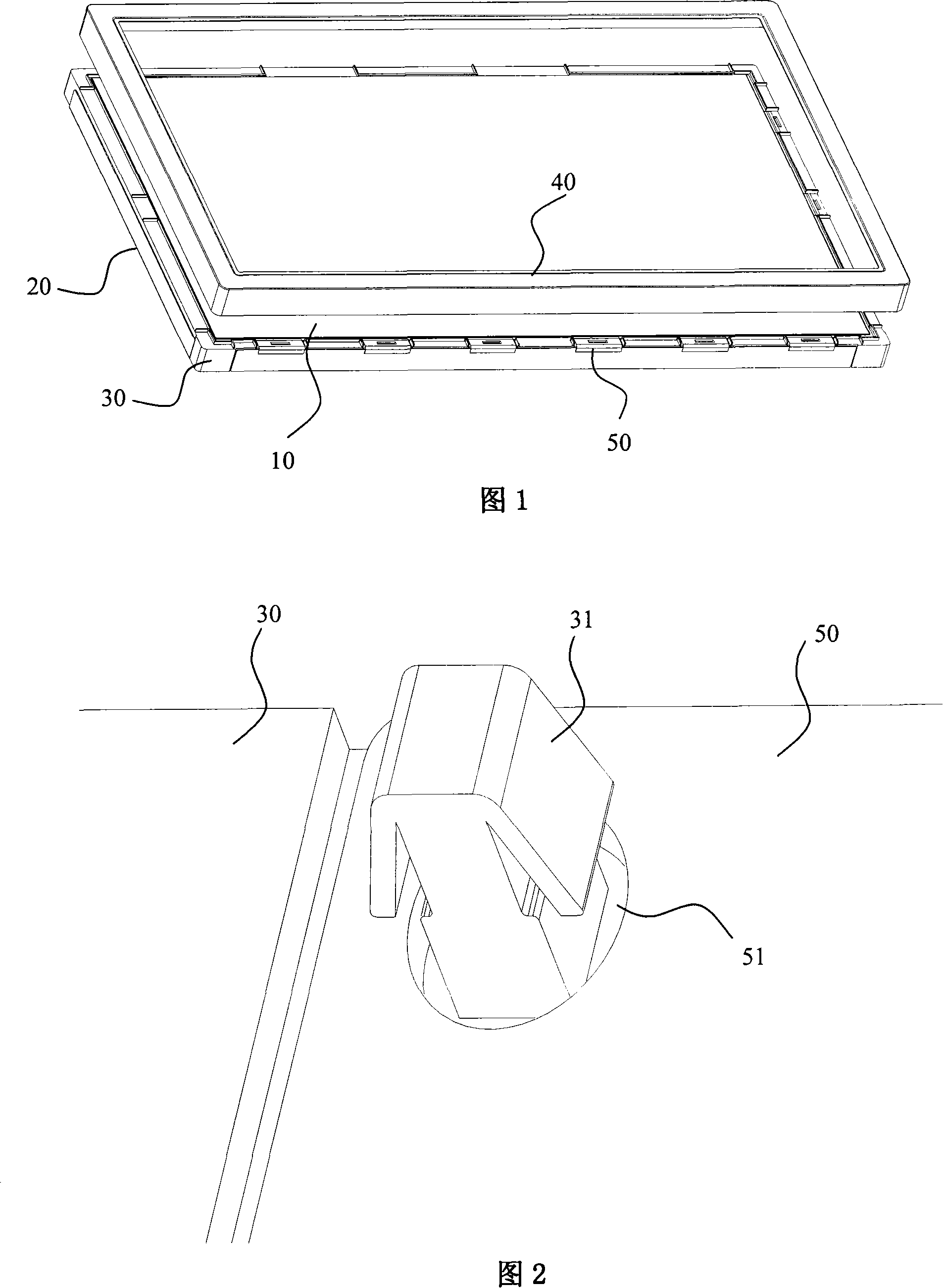
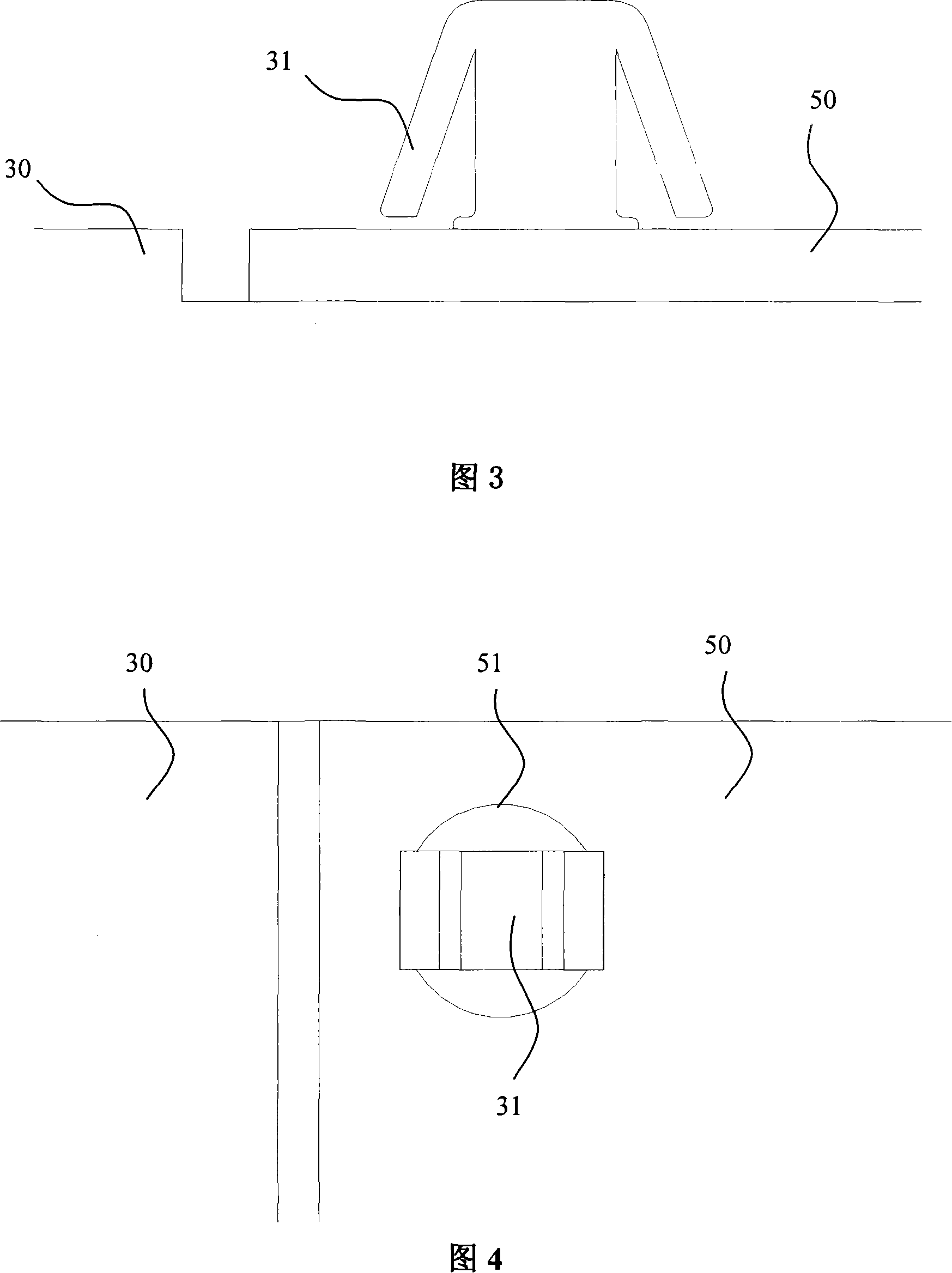
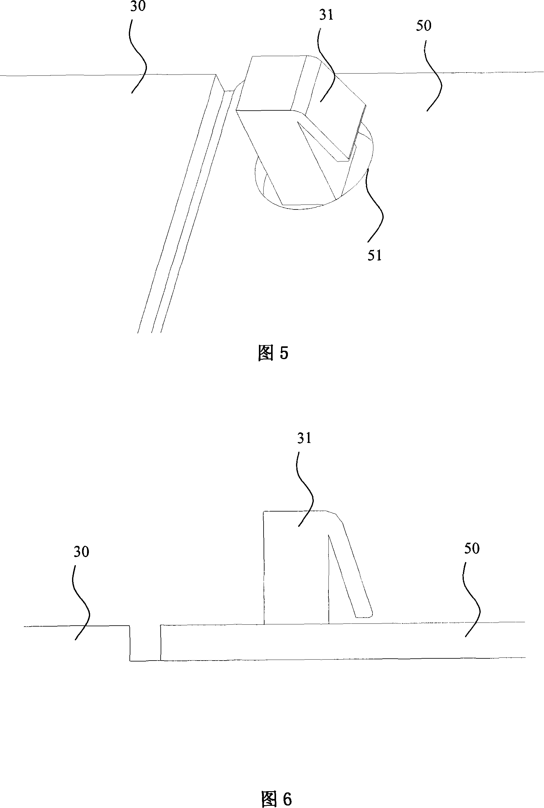
[0027] Referring to Fig. 2, Fig. 3 and Fig. 4, the liquid crystal display module of the present embodiment at least includes a liquid crystal display panel 10, a backplane 20, a first frame 30, a second frame 40 and a PCB board 50, and the first frame 30 is placed On the back plate 20, the second frame 40 covers the first frame 30, and the liquid crystal display panel 10 is accommodated in the first frame 30; the PCB board 50 is fixed on the first frame 30; The frame 30 is provided with a hook 31 , and the PCB 50 is provided with a hole 51 corresponding to the position of the hook 31 . In a preferred embodiment, the first frame 30 is a plastic frame, and the second frame 40 is a metal frame.

[0028] The liquid crystal display panel 10 includes a first substrate, a second substrate, and a liquid crystal layer filled between the first and second substrates (not shown in the figure); the first frame 30, the second frame 40 To position the liquid crystal display panel 10 and the...


PUM


Abstract

This invention discloses a sort of liquid crystal display die set. It consists of a backboard, a first framing which is laid in this backboard, a second framing which is covered in the first framing, a liquid crystal display panel which is laid in the first framing, a PCB plate which is fixed in the first framing. This first framing has the grab, and this PCB plate has the clip core which corresponds to the grab. This invention adopts the grab orientation configuration to fix the PCB plate, it solves the assemblage problem and the resolving problem of the PCB plate effectively, it predigests the assemblage, and it saves the production time and the manpower cost.

Description

technical field [0001] The invention relates to a liquid crystal display module, in particular to a liquid crystal display module which is easy to fix and disassemble a printed circuit board (PCB). Background technique [0002] A liquid crystal display module ("LCM" for short) generally includes a liquid crystal display panel, a backlight module, and a plurality of frames for fixing the liquid crystal display panel and the backlight module. Referring to Fig. 1, the existing liquid crystal display module includes a liquid crystal display panel 10, a back plate 20, a first frame 30, a second frame 40 and a PCB board 50, and the liquid crystal display panel 10 includes a first substrate oppositely arranged , the second substrate and the liquid crystal layer (not shown in the figure) arranged between the first substrate and the second substrate, the first frame 30 is fixed on the back plate 20, and the second frame 40 covers the first On the first frame 30, the space surrounded...

Claims


Application Information

Patent Timeline
Patent Type & Authority Applications(China)
IPC IPC(8): G02F1/133H05K1/02
Inventor 陈德凯
Owner 上海广电光电子有限公司
Why Eureka
Try Eureka