Supercharge Your Innovation With Domain-Expert AI Agents!

Objective lens actuator, diffractive optical element, and optical pickup device

A technology of diffracted light and adjuster, applied in optical components, optics, optical recording heads, etc., can solve the problems of increasing the size of the movable housing, increasing the mass of the balance weight, and reducing the high-order resonance frequency.

Inactive Publication Date: 2008-03-26
RICOH KK
View PDF5 Cites 1 Cited by
  • Summary
  • Abstract
  • Description
  • Claims
  • Application Information

AI Technical Summary

Problems solved by technology

However, using such a mirror frame entirely for the objective leads to an increase in the size of the movable housing and an increase in the mass of the balance weight for the objective, mirror frame, and movable housing
An increase in size and an increase in mass leads to a decrease in the frequency of higher-order resonances
In particular, when fixing a built-in objective lens assembly using a mirror frame with a large mass and moment of inertia by welding or the like, the influence of deterioration of high-order resonance characteristics is extremely large due to insufficient welding rigidity

Method used


Image

  • Objective lens actuator, diffractive optical element, and optical pickup device
  • Objective lens actuator, diffractive optical element, and optical pickup device
  • Objective lens actuator, diffractive optical element, and optical pickup device

Examples


Embodiment Construction

[0086] Exemplary embodiments of the present invention are described in detail below with reference to the accompanying drawings. Like reference numerals designate corresponding elements throughout the figures.

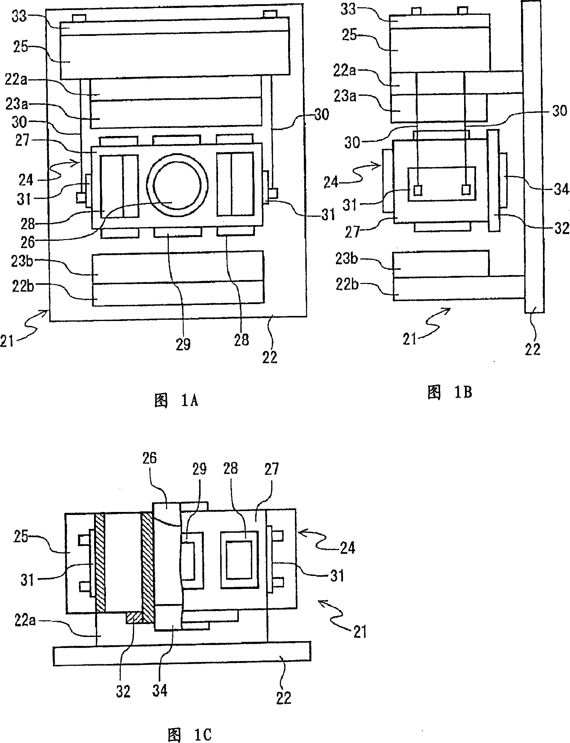
[0087] Fig. 1A is a front view of an objective lens adjuster according to a first embodiment of the present invention. Fig. 1B is a side view of the objective lens adjuster shown in Fig. 1A. Fig. 1C is a bottom view of the objective lens adjuster shown in Fig. 1A. In FIG. 1A, the vertical direction of the paper surface is the tangential direction on the optical disk, the direction perpendicular to the paper surface is the focus, and the horizontal direction of the paper surface is the radial direction (tracking direction). In the following description, both the vertical direction and the horizontal direction are based on FIG. 1A.

[0088] The objective lens adjuster includes a stator unit 21 mounted on the optical information recording / reproducing device. The stato...


PUM


Abstract

An objective lens is directly fixed to one surface of a lens holder. Driving coils that generate focusing thrust and tracking thrust are provided in the lens holder, which is elastically supported by supporting springs according to an amount of thrust generated by the driving coils. A compatible diffractive optical element that outputs a laser beam and is compatible with a reflection signal of the laser beam is directly fixed to the lens holder on the rear side of the objective lens. An inertia ballast is provided on the other surface of the lens holder.

Description

[0001] This application includes by reference the application number 2006-253053 filed in Japan on September 19, 2006, the application number 2006-310093 filed on November 16, 2006, and the application number filed on November 24, 2006. 2006-316732 and priority documents filed on December 28, 2006 with application number 2006-353594 and claiming priority from these documents. technical field [0002] The invention relates to an objective lens adjuster, a diffractive optical element, and an optical pickup device. Background technique [0003] Objective lens adjusters have been used in optical pickup devices and the like to apply focus control and tracking control to the objective lens. For example, Japanese Patent No. 3754225 and Japanese Application Nos. 2005-310315 and 2004-103076 disclose an objective lens adjuster that controls the positioning of the objective lens at high speed by direct electrical adjustment of a drive coil. [0004] In order to control the objective l...

Claims


Application Information

Patent Timeline
IPC IPC(8): G11B7/09G11B7/135G02B7/02
Inventor 田中聪弘中沼宽
Owner RICOH KK
Features
  • R&D
  • Intellectual Property
  • Life Sciences
  • Materials
  • Tech Scout
  • Unparalleled Data Quality
  • Higher Quality Content
  • 60% Fewer Hallucinations
Learn More